
Abbott Analytical Products
1> Inventory the materials prior to start of assembly.
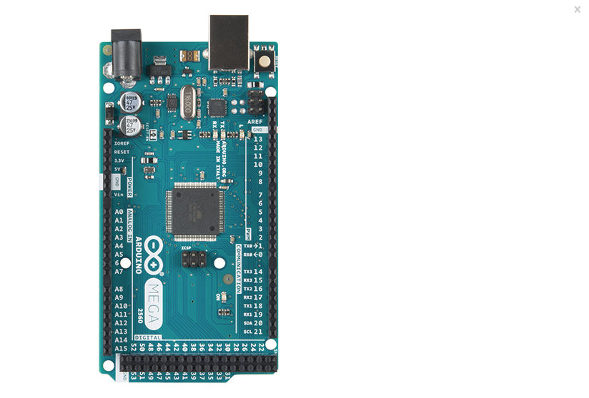
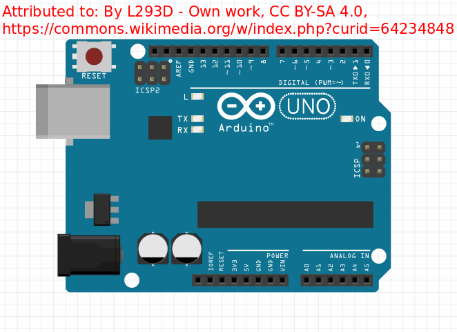
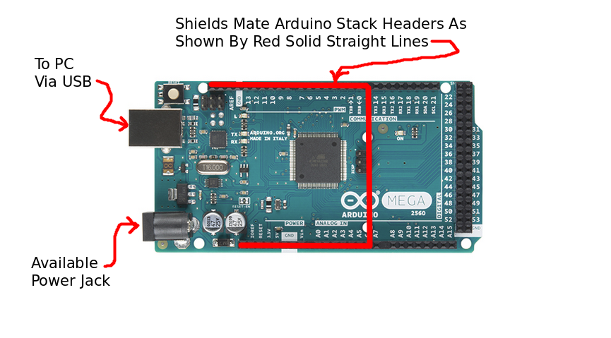
2> Secure appropriate pin layout (MEGA256 Arduino or Arduino Uno) for reference.
2.3> Place Arduino board on a solid insulated flat surface.
2.4> Without connecting the Arduion to USB or power yet, continue to "build".
2.5> As each Shield SubAssmebly is completed, mate it to the Arduino board.
2.6> Once all Shield SubAssmeblies have been mated to the Arduino
2.6.1> Connect the Arduino to the PC via USB.
2.6.2> Power-on the PC.
2.6.3> Verify that the Arduino has a Power-On status LED visble.
2.6.4> Power-off the Arduino USB and proceed with the build of the hardware..
3> Stepper Motor Control Shield Subassemblies:
3.1> Adafruit Motor Sheilds:
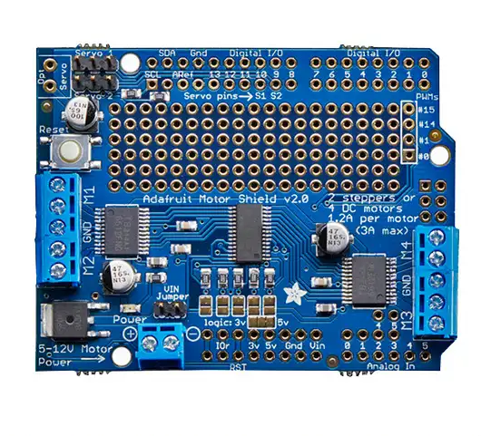
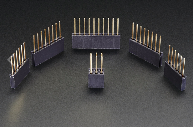
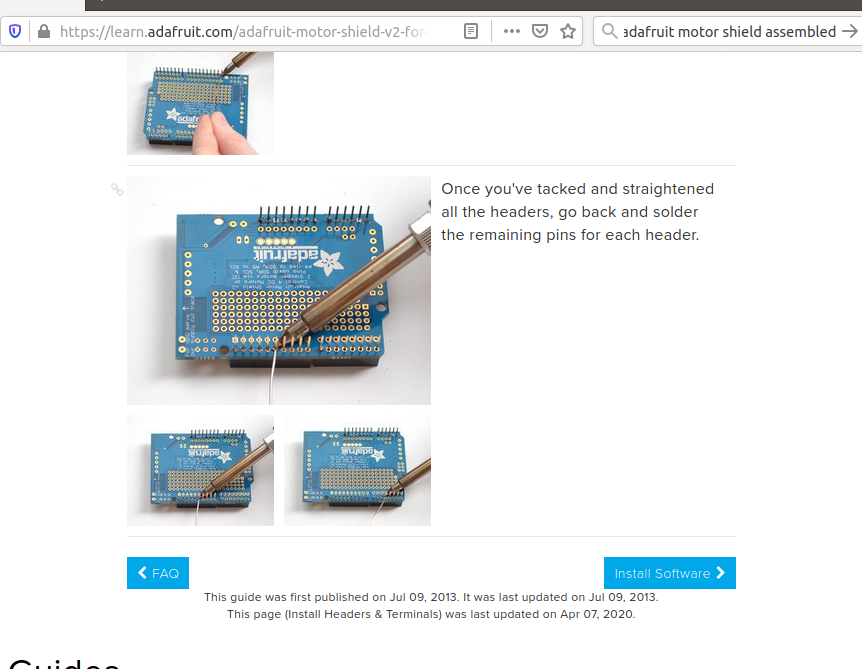
Two Adafruit Motor Shields v2.3 are required to control the stepper motors. The two shields provide four axes xyza CNC capability of the Chickadee Ventilator Simulator Platform. The bad news is that their require a corresponding set of five stacking headers per shield to be "soldered". Adafruit provides a good set of instructions on how the order the headers and perform the soldering operation.
Scroll down the Adafruit web page to:
3.1.3> Solder the five Stacking Headers to each Adafruit Motor Shield per 3.1.1
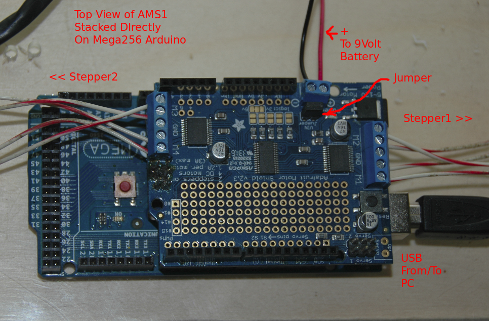
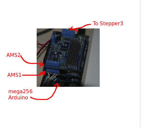
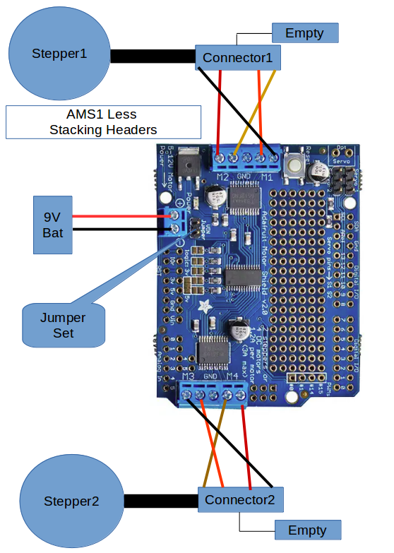
3.1.4> Designate one of the Adafruit Motor Sheilds as AMS1
3.1.4.2> Orient the AMS1 shield as shown in 3.1.4.1.
3.1.4.3> Connect the battery cable and jumper.
3.1.4.4> Kludge the connection between Connector1 and AMS1.
3.1.4.5> Kludge the connection between Connector2 and AMS1.
3.1.4.6> Insert the AMS1 as the first shield of the Arduino
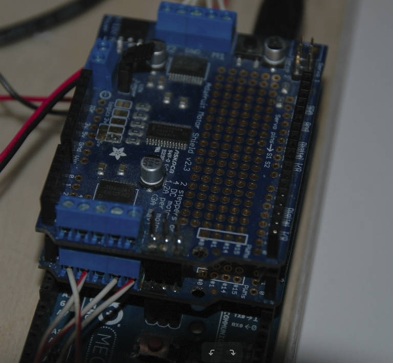
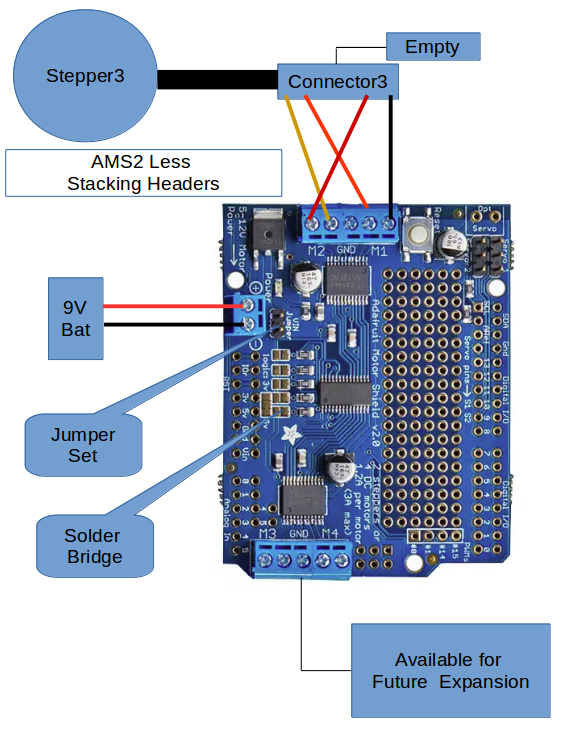
3.1.5> Designate one of the Adafruit Motor Sheilds as AMS2
3.1.5.2> Orient the AMS2 shield as shown in 3.1.5.1.
3.1.5.3> Connect the battery cable and jumper.
3.1.5.4> Create the solder brdge between pads
3.1.5.5> Kludge the connection between Connector1 and AMS1.
3.1.5.6> Insert the AMS2 as the second shield of the Arduino
3.1.6> As needed see reference cited below for Stepper Motor assistance
| Comment
|
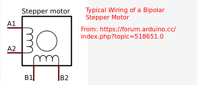
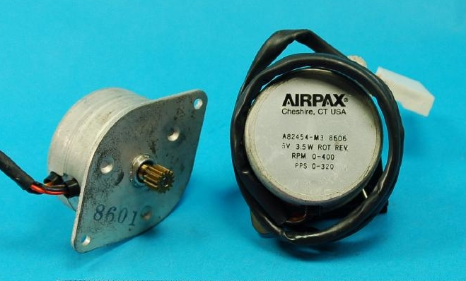
Derived at benchtop: Airpax A82454 M3 Stepper Motor Wiring Four Wire Stepper Version
Shield Terminal Block Stencile Marking
"M1" or "M3" Adafruit Motor Control Terminal Block refer to DC motor 1 and/or 2
Brown
Red
Empty
Orange
Yellow
Shield Terminal Block Stencile Marking
"M2" or "M4" Adafruit Motor Control Terminal Block refer to DC motor 3 and/or 4
|
|
Stepper Motor Test section for instructions for connecting steppers and power to the Motor Shield. URL:** https://learn.adafruit.com/adafruit-motor-shield-v2-for-arduino?view=all
|
|
Various approaches for determing stepper motor wiring. URL:** http://www.piclist.com/techref/io/stepper/wires.htm
|
|
Discussion on stepper motor characteristics/definitoins URL:** https://www.nidec.com/en/technology/motor/basic/00032/
|
3.2> Proceed with the build of the hardware.
4> Seeed SD Card Shield
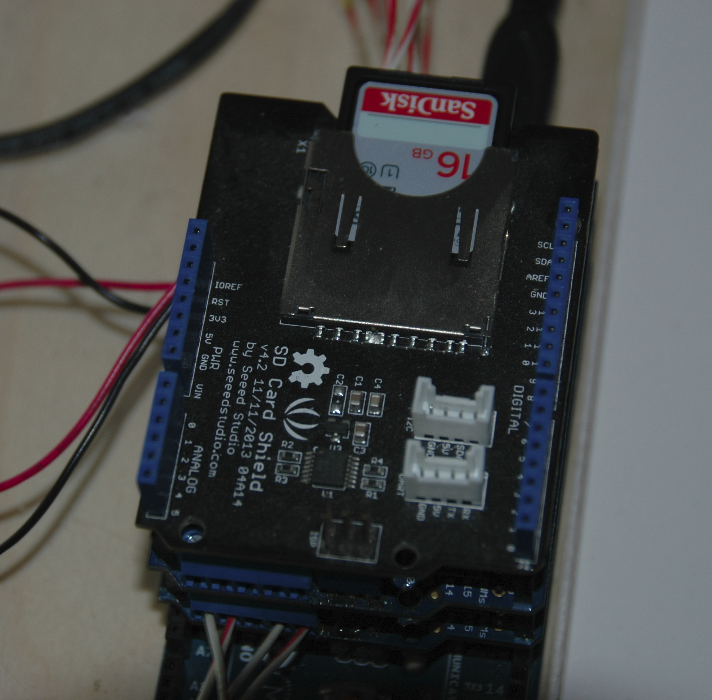
4.1> The Seeed SD Card Shield does not require any further aeembly. Just install an SD Card to make it functional. Note the Seeed Card Shield does not have a Power-on Status LED.
4.2> Insert the Seed SD Card Shield as the third shield of the Arduino
4.3> Proceed with the build of the hardware.
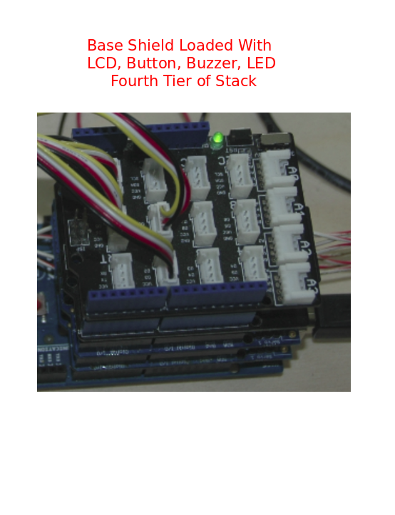
5> Base Shield + Devices
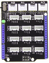
5.1> Install the Seed Grove Base Shield (See the Seed Grove Starter Kit Rally Point).
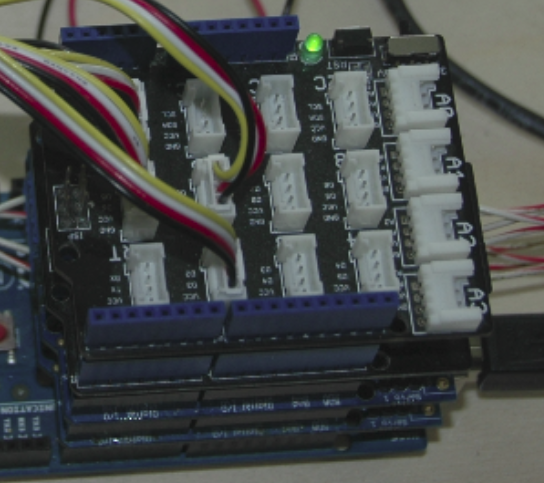
5.1.1> All device connect to ports on the Base Shield via the four wire connectors.
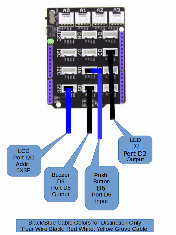
5.1.2> Connect the LCD to the any of the I2C ports on the Base Shield. The
address of the LCD is set at manufacture. As an I2C device the
Arduino will "pick-up" this address along the I2C bus.
5.1.3> Connect the Buzzer to port D6.
5.1.4> Connect the Push Button to port D5.
5.1.5> Connect the LED to port D2
5.2> Insert the Base Shield as the fourth shield of the Arduino
5.3> Proceed with the build of the hardware.
6> Relay Shield + Solenoid Valve Subassembly:
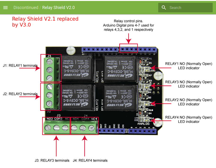
6.1> SEEED Relay Shield:
6.1> Install the Seed Relay Shield on top of the Arduino stack.
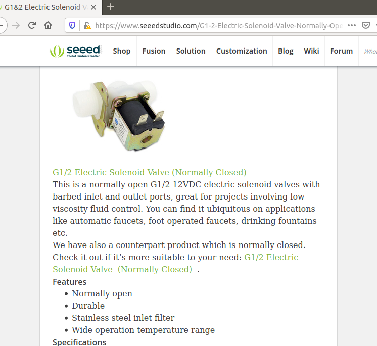
NOTE: The Inlet and Blled-Off Valves Have not yet been secured/purchased.
As a substitute 12V lights will be used in place of the valves.
6.2> Install the Inlet Valve
6.2.1> Assign Inlet Valve to Relay 1
6.2.2> A fix wire from Light Bulb-Inlet to Com1
6.2.2> A fix wire from Light Bulb-Inlet to Power Source
6.2.2> A fix wire from Power Source to NO1
6.3> Install the Bleed-Off Valve
6.2.1> Assign Inlet Valve to Relay 3
6.2.2> A fix wire from Light Bulb-BleedOff to Com3
6.2.2> A fix wire from Light Bulb-BleedOff to Power Source
6.2.2> A fix wire from Power Source to NO3
6.3> The Hardware build has completed. Return to the main page
to start the Check-Ride.
NOTICE: This site was fabricated for best viewing using
Netscape 4.x, or a functionally
equivalent browser.
Please send comments or questions using e-mail, voice telephone at 919-846-7705. (Last update: Nov 25, 2019 tar)