
Abbott Analytical Products
Contents of Page
This web page contains a more technical discussion of how the hardware components were assembled itno a working squirrel-cahse vehicle.
NOTE: Sections of this page may "re-uses" photos and images from prior Abbottanp published projects. As such the images may be
different but still instructive.
Hardware Preliminaries
1> Inventory the materials prior to start of assembly.
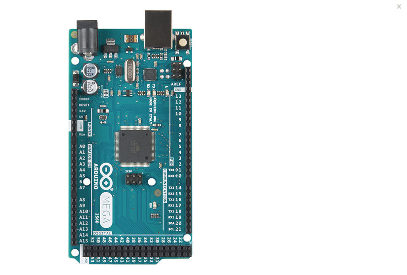
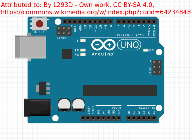
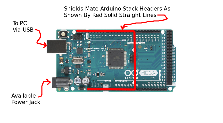
2> Secure appropriate pin layout (MEGA256 Arduino or Arduino Uno) for reference.
2.3> Place Arduino board on a solid insulated flat surface.
2.4> Without connecting the Arduion to USB or power yet, continue to "build".
2.5> As each Shield SubAssmebly is completed, mate it to the Arduino board.
2.6> Once all Shield SubAssmeblies have been mated to the Arduino
2.6.1> Connect the Arduino to the PC via USB.
2.6.2> Power-on the PC.
2.6.3> Verify that the Arduino has a Power-On status LED visble.
2.6.4> Power-off the Arduino USB and proceed with the build of the hardware.
2.6.5> Plug the 9 Volt battery power adapter (without the battery connected) into the Arduino.
3> Stepper Motor Control Shield Subassemblies:
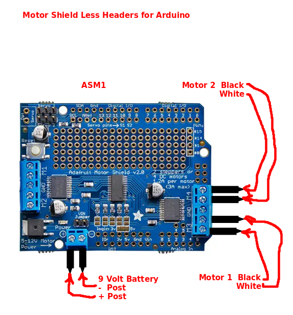
3.1> Adafruit Motor Sheilds:
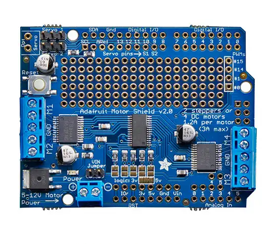
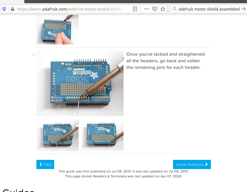
One Adafruit Motor Shields v2.3 is required to control the stepper motors. The shield provide two connection blocks that capable pf supporting a total fo four DC motors.
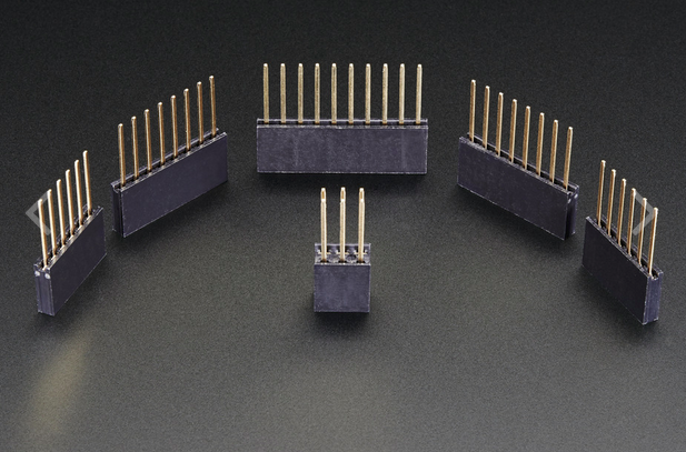
The bad news is that they require a corresponding set of five stacking headers per shield to be "soldered". Adafruit provides a good set of instructions on how the order the headers and perform the soldering operation.
Scroll down the Adafruit web page to:
3.1.3> Solder the five Stacking Headers to each Adafruit Motor Shield per 3.1.1
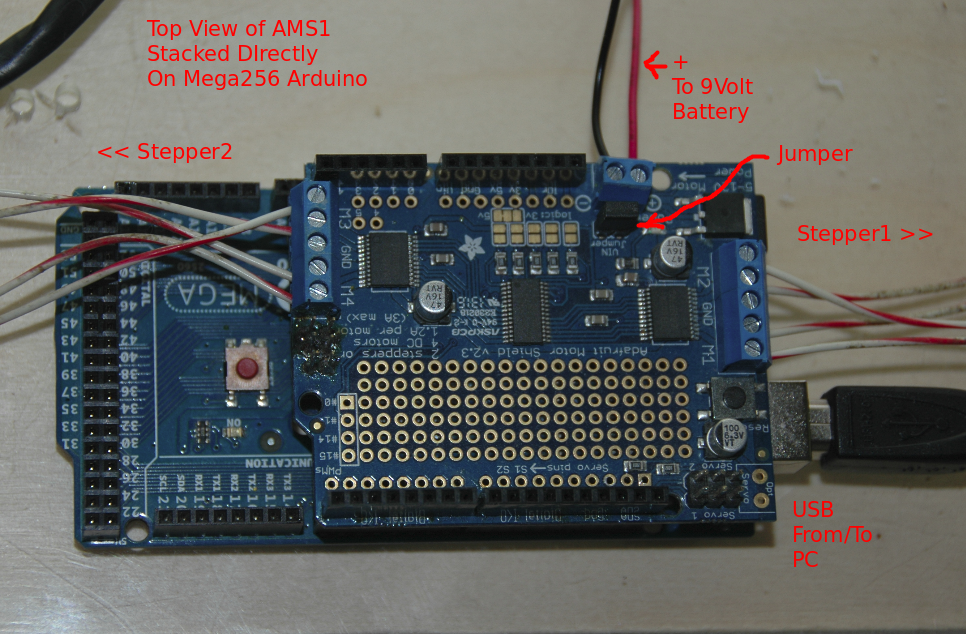
3.1.4> Designate the Adafruit Motor Sheilds as AMS1
3.1.4.2> Orient the AMS1 shield as shown in 3.1.4.1.
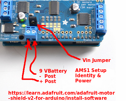
3.1.4.3> Connect the battery cable and jumper.
3.1.4.4> Kludge the connection between Motor1 and AMS1.
3.1.4.5> Kludge the connection between Motor2 and AMS1.
3.1.4.6> Insert the AMS1 as the first shield of the Arduino
3.2.5> Plug the 9 Volt battery power adapter (without the battery connected) into the Shield's power block and install jumper.
3.2> Proceed with the build of the hardware.
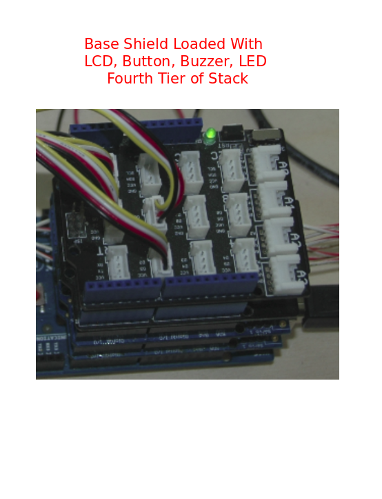
5> Base Shield + Devices
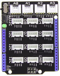
5.1> Install the Seed Grove Base Shield (See the Seed Grove Starter Kit Rally Point).
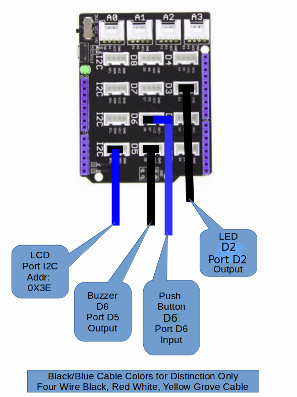
5.1.1> All device connect to ports on the Base Shield via the four wire connectors.
5.1.2> Connect the LCD to the any of the I2C ports on the Base Shield. The
address of the LCD is set at manufacture. As an I2C device the
Arduino will "pick-up" this address along the I2C bus.
5.1.3> Connect the Buzzer to port D6.
5.1.4> Connect the Push Button to port D5.
5.1.5> Connect the LED to port D2
5.2> Insert the Base Shield as the fourth shield of the Arduino
5.3> Proceed with the build of the hardware.
6> WIFI Shield:
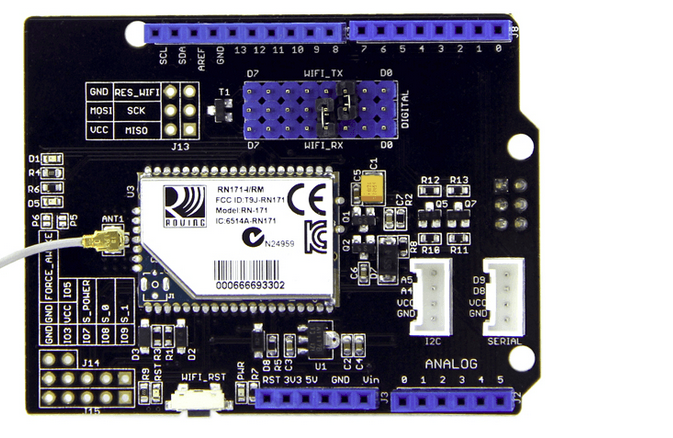
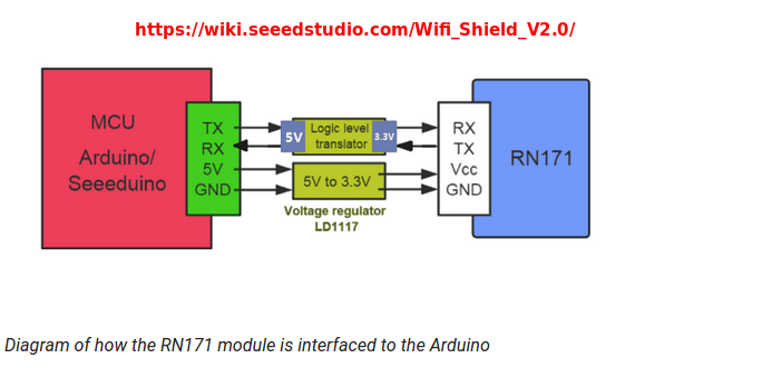
6.1> SEEED WIFI Shield:
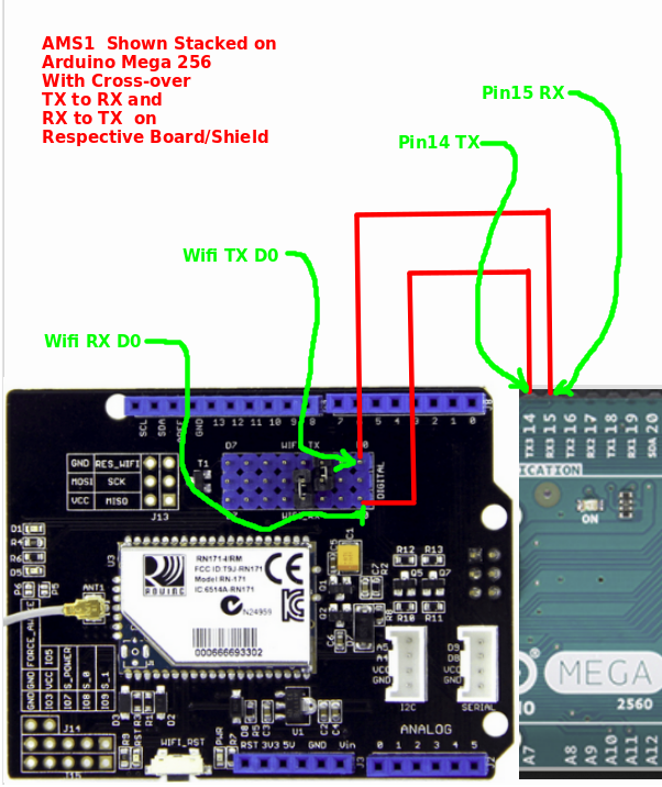
6.1> Install the Seed WIFI Shield on top of the Arduino stack.
A cross-over between the Mega256 Pin14-TX to Wifi RX D0
A cross-over between the Mega256 Pin15-RX to Wifi TX D0
6.2> Connect the Arduion Mega 256 to the WIFI Shield to obtain the "cross-over".
7> Vehicle Chassis:
7.1> Vehicle Considerations:
-
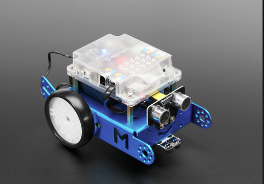 Makeblock MBot for sale at Adafruit for $99
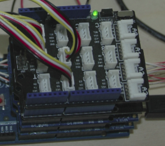
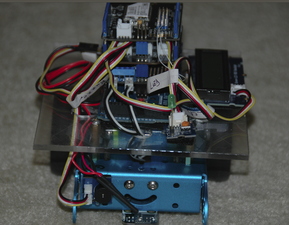 Stacked, racked, and ready to roll
 Stacked, racked, and ready to roll
The MBot chassis less its elctronics was selected to serve as the platform for this demonstartion.
The MBot's motors, spacers, wheels, and roller were re-used. A larger deck was employed to accomoddate
extra devcies.
Adantages:
- It was on-hand in the shop/lap.
- Its characteristics were known.
Disadantages:>
- Grossly underpowered.
- Wheeled for smooth surfaces instead of tracked or equiped with balloon wheels.
- Low ground clearance.
- Power roller turn response.
7.2> Using the vehicle chassis of choice mount the Arduino stack, accessories, and DC power batteries.
7.2.1> The Arduino board and the Adafruit Motor Shields v2.3 both have power jacks to accommodateDC batteries.
7.2.1.1> The standard Arduino plug and 9volt connector were employed.
7.2.1.2> The Motor Shield external power connector block was used to secure the second 9volt source for the motors.
7.2.1.3> The mounting the batteries physically on the vehicle was finally acheived by rubberbanding the two togeter.
This banding formed a cell pack which was them rubberbanded to the vehicle.
7.2.2> The accessories were velcro-ed to the vehicles chassis.
7.3> The Hardware build has completed. Return to the main page
to start the Check-Ride.
NOTICE: This site was fabricated for best viewing using
Netscape 4.x, or a functionally
equivalent browser.
Please send comments or questions using e-mail, voice telephone at 919-846-7705. (Last update: September 8 tar)