| Image | Comment |
|---|---|

|
Three axis CNC prototype. Bottom to top: Arduion Mega256, Motor Shield 1, Motor Shield 2, SD Memory R/W Shield, Base Shield. Extended from the Base Shield are the LCD from I2C port1 and LED from digital port2. X-Axis and Y-Axis steppers extend from Motor Shield 1. Z-Axis extends from Motor Shield 2. Devices extending from Base Shield digital ports 5 and 6 were not implemented as a part of this project. |

|
Three low cost stepper motors are used to dirve the prototypes three axes. A stepper motor connects to its allocated controller board connection terminal block. Consult the controller board vendor's terminal block pinouts. The stepper motor vendor's documentation will also need to be consulted to determine the corresponding pin assignments. As shown in the image, the user may need to creatively interface the steppers to the Motor Controllers. |

|
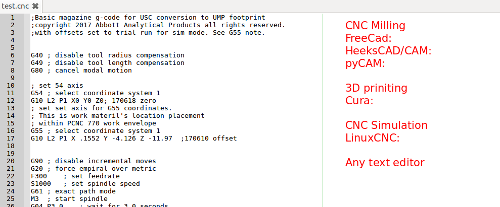
The a021_xystepper project code (*.ino, *.h, *.png) reside in the appropriate GITHUB respository (CopyPaset URL**: https://github.com/trooker/a021_xystepper. That repository also contains the "test.cnc" file that was used for validation testing. The "test.cnc" is a Unix/Linux file so the end-of-line will be different than that of a Windows text file. |

|
These libraries need ot be added or included (depending upon the IDE used) to the project prior to verification and uploading of the a021_xystepper project code bundle to the Arduino board. |
|
"test.cnc" gcode file provides a set of commands that embeds information that a CNC lathe, CNC mill, or 3D printer need to render a physical likeness of the design of interest to the user. There are numerous ways to create and edit a gcode files such as test.cnc. The gcode file extension may vary depending upon the target rendering machine. Typically a CAD/CAM tool is used to generate the bulk of the gcode. The designer/engineer augments the gcode as need to obtain specific effects.
The three images below show the evolution of the a design into a set of gcode commands. The intial starting point is a sketch of the design. The sketch is submitted to CAD/CAM tool 


|

|
LCD exhbitis the parsed line of gcode that directs a specifc mode of movement along the X-Axis. See line 82 of test.cnc. |

|
LCD exhbitis the parsed line of gcode that directs a specifc mode of movement along the Y-Axis. See line 96 of test.cnc. |