
Abbott Analytical Products
Reference:
Brass Credit Card:
Brief Summary of Project:
From 2022: (FreeCAD and LinuxCNC) A friend requested the fabrifcation of a credit card formatted nameplate for one of our mutual
associates. Having gained experience since the 2018 Brass Nameplate project, FreeCAD was employed for
design and generation of gcode.
FreeCAD is an opensource CAD tool that allows the design of objects and subsequent gcode (program for executing
the actual LinuxCNC milling of the object.
| Image
| Comment
|

|
This image shows the final delivery of the Credi Card Style nameplate. The design was rendered
using FreeCAD 18.4 running under Ubuntu 16.04 (64Bit). The FreeCAD design artifacts and final
gcode programs are available for downloading form the GitHub link given below.
https://github.com/trooker/credit_card_style_3line_nameplatete
|
|
Lower Level Detail
|
|
FreeCAD View

|
Snapshot From FreeCAD Design
| Image
| Discussion
|

|
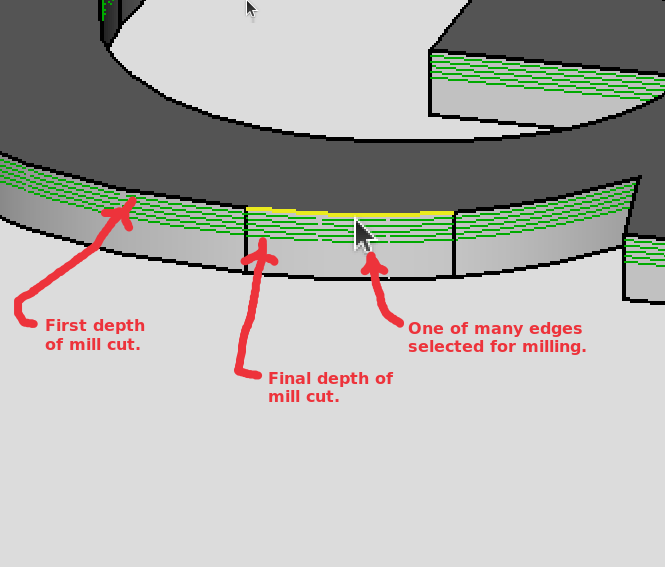
These images are of the "Engrave" task definition showing the "G" of the third line. In this instance
the designer has elected to sequnetially "highlight" one of the 1324 endges required to define
the three lines of charcters. The image also shows the "Engrave" task five depths that FreeCAD
rendering of the design created. This rendering yielded the first gcode program for milling the
Credit Card Three Line design.
|
|

|
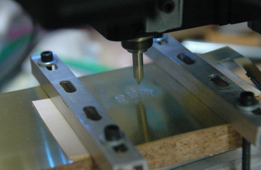
This image displays the LinuxCNC program driving the FreeCAD produced gcode on a Sherline
8580 NexGen CNC in a simulation mode. The engraving bit sat idle while the user observed the
simulation run.
Based upon the simulation run a decision was made to "modify" the original FreeCAD gcode. The
modification employed various used defined variable for x-, y-, and z-axis speeds, a "safe height
to which the bit was raised in the z-axis for relocation. The modification also consolidated the
actual engrave loop for milling the three lines of text.
|

|
First pass using the engraving bit used for projects in 2018 and 2019. This first attempt was rule
unacceptable quality. That led to a search for a "tighter" engraving bit using the same edges.
Introducing the new Dremel Engraver tool to the project required a new entry in the tooltable and
minor changes to FreeCAD artifacts as well as the gcode.
|
|
Helpful Approaches
|
These modifications greatly improved the original gcode from FreeCAD
|
Flatness Check

|
A gcode program was written which verifies that the four corners of the brass stock are flat
with material secured using the project hold-down fixturing. This project's flatness test reuses
gcode fragemnts from the Fishing Lure lip checks.
|
Major Tweak to gcode


|
The original FreeCAD engrave process for the three lines of textrequired 6196 separate movements
to make five separate levels of depth cuts. In other words the engraving bit would would follow
the same path to create the three lines of text five separate times. The only difference would be the
increasing depth to which the engraving bit would plunge. Using the LinuxCNC subroutines
to control the program flow (the movement of the engraving bit) an engraving loop was created
using "one pass" of the original FreeCAD gcode and a logic while less than to check to see which
loop to do next or to break-out of the loop.
This essentially allowed a "single step through a depth, halt, check". In that manner when the results appeared
to be "satisfactory" the milling phases was terminated.
|
Results


|
The final approach that was found to be helpful during the actual milling of the Credit Card
Style Nameplate was adding the same type of "single step through a depth, halt, check" approach
was implemented for the Contour-Fillet-Tab to generate the appearance of the credit card style.
|
|
|
|
Brass Nameplate:
Image 2019: Second Brass Design Production demonstrating movement down learning curve.
In 2019 the usage of FreeCAD replaced pyCAM and HeekCNC. Two different engraving styles and bits
were employed to allow client to select preferred style. Finaly, c-shaped adjustable hold-down brackets
greatly improved fabrication quality. FreeCAD provided a "Tab" contouring feature that gave extra control
during the final milling.


Brief Summary of Project:
From 2018: (OpenSCAD/PyCAM/HeeksCNC/LinuxCNC) A brass nameplate for use on the display of a model of the USS Constellation was milled. It was a
simple three line affair with two drill holes of brass tacks set on a thin oval brass blank. It was a very real learning experience
in homing, tool heights, work offsets, tabs, and Heeks CAD/CAM tool. There were multiple runs made in wood and scrap copper. But
there was only one piece of scrap brass created. That run demonstrated the need for tabs as the holddown fixturing failed. The final run was a step process
involving three tool changes. In order to do that at the skill level at that time, three separate NGC programs were sequentially run.
Image 2018: First Brass Design Prototype displaying hold-down failure and need for tabs.

From 2018: Discussion of Process Flow
The gcode shown below is ordered in the sequence used to mill the project. Note that that engrave and blank milling employed
the usage of user defined variables and o-code
flow control looping.
- Engrave text
- Center drill two holes along centerline of raw blank.
- Milling blank in four passes with tabs.
Tool Table Entries
- T4 P4 Z1.627 ;1/8 flat end mill 3/8 holder
- T5 P5 Z0.9975 ;center drill#2 in collet
- T7 P7 Z0.7865 ;router engrave bit collet
Design to gCode Process Flow
1> Use OpenSCAD to create ellipse shape.
2> Using the 2D shape export it as a SVG image from OpenSCAD.
3> Invoke pyCAM and set units to inches.
3.1> From the main bar menu select Edit -> Engrave text to obtain the
Engrave text
Wizard. Enter the text needed and
apply.
3.3> Push this "text" through the pyCAM process for Tools, Process, Bounds, Task, and Generate Toolpath. Then
Export the process engrave text model as an
ngc file from pyCAM.
4> Invoke HeeksCAD.
4.1> Import the SVG image (step 2 above) and extrude for solid shape.
4.2> Add the two drill holes as points.
4.4> Setup Drilling operations for the
two Holes.
4.5> Define the end mill tool (T4) and the center drill tool (T5)for cutting the blank shape using the values in the tool table given earlier.
4.6> Attempt to execute the Post-Process. If successful this activity will allow the creation of an gcode ngc file.
4.8> If desired, a text editor add user defined variables and o-code flow control looping to improve readability.
4.9> Using a text editor split the "blank/drill hole" ngc into two separate ngc files to facilitate tool changes.
5> For a trial run, open a LinuxCNC session (ideally on a simulator) engaging the stepper motors.
5.1> Load the appropriate tools to the tool table(T4, T5, and T7) to satisfy the newly created ngc gcode files.
5.2> Load the "blank" ngc gcode file to LinuxCNC, execute with the steppers engaged. Make the drill hole
tool change per the NGC. Finally, do not sweep away the "red" mill path lines.
5.3> Load the "engrave ngc gcode" and adjust position (using Touch Off G54 in X,Y axis) as needed to center the text box on the blank.
5.4> Inspect the "composite" engrave text box and the blank from the
Z-axis and
Y-axis.
7.1> Load the "blank" ngc gcode file to LinuxCNC, execute without the steppers engaged. Do not sweep away the "red" mill path lines.
7.2> Zero the
engraving ngc as in step 5.3 and execute using
step movement. Use the "step" through execution until comfortable with to very placement and depth of engrave text.
Plexiglass Heart:
(Veus/PyCAM/HeeksCNC/LinuxCNC) The classic heart shape was created in such a way as to be completely scalable in the XY plane. The
hearts have text. The first runs were executed in Plexiglas. After a number of prototypes, a suitable level of "quality" was
obtained to allowing gifting the resulting objects as tokens. The plan is to use the heart shape on a box lid eventually.
Image 2: Early prototype showing crude tab removal and poor junction points.

Discussion of Process Flow
The gcode shown below is ordered in the sequence developed/used to mill the project. Note that that engrave and blank milling employed
the usage of user defined variables and o-code
flow control looping. The Heart Blank goes one step further using
scaling in the XY plane.
Heart Blank Design Supporting Artifacts
- Spreadsheet rendering of the classic Heart Curve.
- SVG file exported from Veusz based on classic Heart Curve.
- HeeksCNC project file yielding gcode.
gCode for Milling
- pyCAM produced Engrave Text.
- HeeksCNC generated Milling Blank.
Tool Table Entries
- T7 P7 Z0.7865 ;router engrave bit collet
- T16 P16 Z2.27855 D0.1275 ;1/8 x 3/8 double 2 flute
Design to gCode Process Flow
Heart Component: A suitable set of equations representing the classic Heart Curve was found. A spreadsheet
was used to assmble a graph of the outline of the heart. The data points of the outlined heart were convert to a *.csv format. The
Veusz graphic tool was used to create an XY plot of the *.csv data. Once that was done the figure was exported as an *.svg file. The
*.svg file was imported to HeeksCNC. As an *.svg the heart shape is basically a 2D figure. But
before the heart shape could be used it had to have the extraneous Veusz introduced axis information removed. Once that was done
processing continued. There is no extrusion necessary for a 2D figure, since the same effect can be achived in a Profile Operation. After
setting the tooling and tabs gcode was generated. The "raw" gcode was modified to incorporate o-code program flow control. Scaling of
the XY was achived using global replacement.
Engrave Text Component: Prior engrave experince with pyCAM led to using that tool for the engrave text. A pyCAM session was started. The default model deleted
The the units was switched to "inches". The Edit bar menu item was sleected which resulted in "Engrave text" option becoming available.
Selecting the "Engrave text" option yielded the Engrave text wizzard. Add "Love" and select
Apply to create a new model, Text Love. Adjust the sizing as necessary. The 3D view should
now display. At this point the development to gcode should follow the typical tools, process,
bounds, task, toolpath simulate/export process to yield the appropriate gCode for the "Love" text.
Milling Time: Open a LinuxCNC session. Load and execute the Heart Blank gcode. Once that
set of code finishes load the Engrave Text. Inspect the Engrave Text to insure it is
placed as needed. Relocate/place the Engrave Text as needed using the Touch Off button
process for X/Y axis for P1 G54. When satisfied execute.
Simple Wooden Fishing Lure:
Brief Summary of Project:
(OpenSCAD/HeeksCAD/CNC) Simple Fishing Lure: shape showing the space between the object and the walls of the pocket. The object
rest on the plane-Sketch. The plane-Sketch surface will serve as the "tab/tag" holding surface for milling of the second side. Details are provided at this link.
Image 3: Prototype executed with scrap material.

Waterline Fishing Lure:
Brief Summary of Project:
(OpenSCAD/Blender/FreeCAD) The STL/mesh file was grabbed from the earlier HeeksCNC effort. It was imported and converted into
shape/solid and eventually into a set of waterline NGC code. Waterline refers to the milling pattern that follows
the contours of the shape being milled. A run of saw dust was made using this
design to create the left side of the lure. The stock was then flipped and a second run executed. The
results demonstrated the "feasibility" of the design. But it clearly exhibited a need for additional layers
of waterline cuts and a need for closer control of the "flipped" origin. This original design was discarded
because too much "manual" effort was required to reconcile the right/left side mis-match. Plus the shape was
not an acceptable "lure".
Refinement of the waterline by increasing the granularity of the contour lines (depth of cut from -0.025 to
-0.010) did not provide a suitable quality to justify moving forward with this approach.
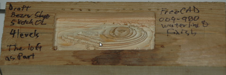
Image 4: Simulation Run in FreeCAD of Waterline and Finishing.

Discussion of Process Flow
The same STL that was imported to the HeeksCNC lure project was reused. The
import process steps for FreeCAD is the same as that used for the box/lid logo. Once the
The code shown below is ordered in the sequence used to mill the project.
- The "starter" CAD file builds the STL
- FreeCAD Waterline Fishing Lure design project.
- Waterline operation yields the surface shape of the lure
- Finishing operation removes material from around lure forming pocket
Tool Table Entries
- T16 P16 Z2.27855 D0.1275 ;1/8 x 3/8 double 2 flute
Collection of Helpful Images
Design to gCode Process Flow
This project reuses an existing OpenSCAD object. This object originally integrated a simple hull function in union with flat planar
surface. Once the object was designed and rendered it was exported as a *.STL file. The file was imported into FreeCAD as a STL mesh
entity. Sequentially that entity is converted to a shape, solid, refined shape, and finally a usable path shape. Once the path shape
was defined a "Job" was created with an ocl waterline operation and a finishing operation. The finishing operation first used a pocket shape to remove
stock material from region between the lure and a bounding box. The finishing operation completed its run by cutting an outline contour
outline of the lure. Tabs were not used since the planar surface was to serve as a base/wall between side 1 and side 2. As originally
planned side 1 would be milled first. Side 1 must also have index registration points to facilitate
flipping and milling of side 2. This will require extending the registration points through the work piece
to what will become side 2 milling surface. (Insure that the registration points do not mar the surface of
the region being milled.)
Side 1:
The waterline operation and the finish operation would run two separate gcode programs under LinuxCNC-Axis. But first the finish job would
be run without the stepper motors being engaged. Once this "virtual" mill job was completed LinuxCNC would display the
tool path executed except indicating a red
tool path . Then load the waterline. Us the "Touch Off" to jockey
X P1 G4 until a suitable
waterline aligns with the "finish" representation. Repeat for the
Y P1 G54. Continue to jockey the waterline
until a "best" balance appears. Try zooming/panning for better
resolution and jockey. Once satisfied run the waterline gcode program. After the waterline program executes, load and run the
finish program.
Side 2:
With Side 1 complete, flip the work piece/stock. Use the previously set index registration points of Side 1
set the physical location of the work piece. Start by loading/running the finish gcode without the stepper
motors engaged. Using the completed finish tool path align the waterline gcode and execute with the stepper
motors engaged. Then complete side 2 by executing the finish gcode.
Conclusion
As originally conceived the lure was to appear as a symmetric hull figure. If all went well, side 1 and side 2
should appear symmetrically spaced when viewed axially along the Z-Y and/or Z-X planes. The difficulty in alligning
the two sides precluded further movement down this avenue.
Complex Surfacing of Wooden Fishing Lure:
Brief Summary of Project:
(OpenSCAD/FreeCAD) A more nartual looking fishing lure has been designed using OpenSCAD with Bezier curve surfaces. The imported
STL mesh file was found to be too complex for PC resources. As a result no usable FreeCad shape was produce.
(OpenSCAD/Blender/FreeCAD) The STL model design effort of the lure shape was imported to Blender. This work is in process.
Image 5: Complex Fishing Lure in OpenSCAD (Flat Nose)

Image 6: Complex Fishing Lure Imported to FreeCAD (Round Nose).

Discussion of Process Flow
Subsequently discovered OpenSCAD "hull() function" and Bezier curved surfacing.
Design Supporting Artifacts
- Design code combines lure component shapes.
- Creates the surface patch for the under-belly of lure.
- Renders a generalized lure shape/surface created.
Design to gCode Process Flow
(OpenSCAD/FreeCAD) The generalized shape of a "crank" fishing lure was created using OpenSCAD. That shape was cut to create a more
realistic lure. The two components were then assembled into the lure shape. That shape was then converted to an *.stl file for
export. It was then imported itno FreeCAD where the complexity of the mesh shape became obvious. It proved to be impractical to
proceed along this approach.
A number of alternate approaches to obtaining a complex solid surface shape are being explored.
Wooden Box with Lid:
Brief Summary of Project:
The intent was to create suitable wooden boxes for general gifting. The project originally started by looking at creating puzzle
boxes with dovetail edges. But reality and CAD skill set collided. Once reality and complexity of FreeCAD's cubes and Path work bench
began to manifest itself, a decision made to slowdown. Then began the effort to make presentable wooden boxes with pockets and lids
with matching pads. The lids were to also have an appropriate logo/design artwork of minor complexity. That level of crafting was
captured in the following project.
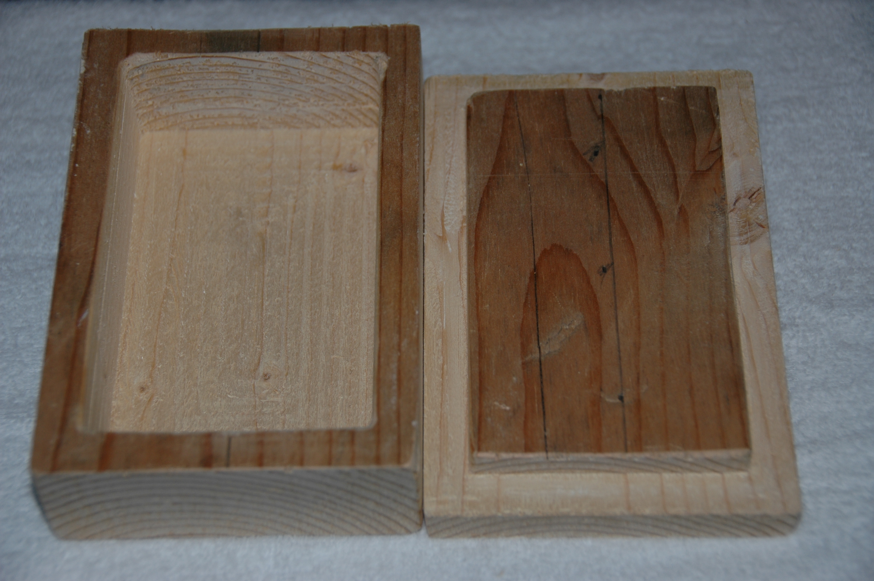
Image 7: Box/Lid/Logo. Wooden pieces prior stain.

Discussion of Process Flow
- (FreeCad) The first run resulted in a usable box/lid. This run involved learning about the complexities of Sketches and setting
constraints. The default Zig-Zag pattern produced overly tedious clean-up work/sanding of the
pocket wall.
-
(FreeCad) A second run has been designed to mill more material from the stock for the pocket/pad. This run employed the original Sketch
from the earlier effort with resizing of the pocket/pad. The Offset milling pattern was
employed. Simulation under LinuxCNC demonstrated a cleaner approach. The simulation of the milling showed an issue with the placement
of the pocket and lid. Re-positioning of the pocket and lid within the virtual stock resolved that
issue. By re-positioning the milling was simplified. It also supported the pocket-pad matching without having to use the mirror or
to set other design features.
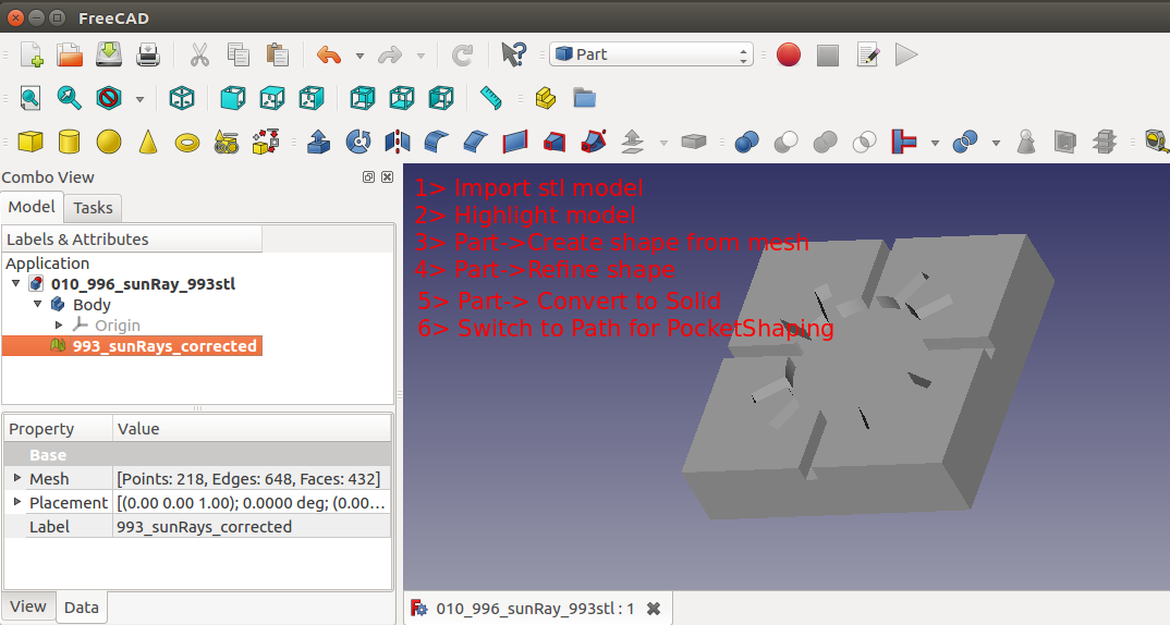
- (OpenSCAD/FreeCAD) A "radiant sun" image was designed in OpenSCAD as a 3D object and exported to FreeCAD as
an STL mesh model. The import went well resulting in body, shape,
solid, path shape, and pocket_shape.
Box/Lid Design Supporting Artifacts
- The supporting FreeCAD and OpenSCAD design project files for the box/lid are download-able as one
zip file.
- The mis-directed dovetail design approach project files are available as a zip file.
gCode for Milling
The resulting NGC gcode from FreeCAD and associated tool table are shown below. The current sizing is for a 6x4x1.5 box. The pocket and pad are roughly 5x3. The pocket is set to 1.3 inches depth. The pad is set to .375 inches.
- Box with pocket.
- Lid with pad. The thickness of the lid is left to the miller's
choice.
- Radiant Sun pocket.
Tool Table Entries
- T3 P3 Z1.273 D0.09375 ; 3/32 end mill Short Sherline 7002 for "radiant sun" logo.
- T18 P18 Z4.459 D0.233 ;1/4 router deep pocket for pocket, pad.
- Large surface removing bit via manual operation of the mill.
Design to gCode Process Flow
(OpenSCAD) The original box/lid involved dovetail edges and a circular pocket as shown the box and
lid CAD drawings. These drawings led to exportable *.stf files.
(OpenSCAD/HeeksCNC) Importing the two *.stl files from above produced the box_tab and
the box_slot projects. Although their where reflective of the intended design objective,
they appeared to be beyond the skill level available for the project.
(FreeCAD) As a good launch into FreeCAD a simpler "box/lid" with pocket/pad matching was initiated. As described and documented
above gcode was produced directly from FreeCAD and saw dust created. After receiving a request for
two more wooden box/lid this project was measured as a success.
Path Forward
- The box lid needs ot be tweaked just a bit to reduce the need for sanding the leading/lagging
edges.
- The next generation of box pocket/lid will employ a dovetail fit to slide the lid open/close.
- Additional "logos" will be added ot the collection.
Evolving a Practical Wooden Fishing Lure:
Brief Summary of Project:
(FreeCAD) A nartual looking fishing lure can designed using the various workbenches of FreeCAD.
This avoids the "resource hogging" associated with improting STL files of lures generated externally.
- Welling Lure Designshop
- Converting simple sketches(https://www.youtube.com/watch?v=7oOWvC80dNw) into complex solids
- Useful sketch and BSpline (https://owncloud.gwdg.de/index.php/s/HS2FD9s49wQs4fI) information/guidance.
Image 8: Post milling of first side of prototype lure.
Discussion of Desgin Process Flow
An original conceptual drawing of a fishlure must be manifested as a draft drawing. This
"lure draft" serves as the "2D container". The defined "lure draft" provides the outline and serves
as the boundary for the additional "shape defining layers". For this version of design four shape
defining layers were generated. At this point the shape defining layers were jockeyed into
appropriate locations to provided the required shape in 2D (X/Y Plane) and
constrained (see Image 9 below). Using the following Best Practices the
complexity of multiple sketches in a drawing surface is reduced.
- Practice with the sketch features before attemtping a "for record" run.
- Constrain as each sketch feature (lines, circles, BSpline, eclipses) is drawn.
- If a sketch is not immediately needed, hide it.
- Draw the structure of sketches in reverse order of the offset to be used like a pyramid. The
smallest sketch, the circle, was assigned to the top, The largest sketch, the outer trace
approximation of the Bezier shape was destined for the the bottom.
Image 9: Sketch of Level 1 (light green) and three sketches (white) overlaid on Bezier shape .

Once the shape defining layers have been constrained the offsetting and lofting can be
performed. The offsetting selected was a pyramid shape with the top layer being set at Z=0.0.
Subsequent shape defining layers were offset in the negative Z-axis. With the offsets defined
the Part was lofted to form "one side" of the lure.
Image 10: Lofted sketches render solid (planar view inverted to show sketch slices)

The generated loft shape of the lure was then submitted for Path Job Operations for waterline,
tabs-contour and pocket shape.
Design Supporting Artifacts
Once the lure has take its solid shape following lofting, it is ready to create the Job. With the
Job defined select the tooling and setup (material offsets and origin) to suit the mill shop and
stock material.
Waterline: Milling Lure Shape
Then define the first operation will define the lure as a 3D Surface solid. That operation was titled Waterline.
The second operation seeks to "free" the lure from the work stock material. For this specific lure
design's Waterline Operation, the starting height was established to be Z=0.0. The ending/lowest
depth was set to Z=-0.375. The cut dpeth was set to .0500. After simulation the depth of cut for
the circle feature was manually set to Z-0.0250.
Finishing: Freeing Lure From Work Stock
The second operation can be named Finish. The Finish Operation sequentially executes Pocket Shape
and Tabs/Contour. The start depth, finish depths, and step down cuts are consistant with those
used for Waterline.
Review of Waterline gCode
Generate the gcode and review the results. For the 3D Surface Waterline there is a specific
need to identify "extraneous loops" as shown in the next image below. An
extranepus loop does not "tie" to a specific waterline-contour. These extraneous loops
should be removed. Locating them is trivial. They typically occur near the point in the Waterline
gcode where step down cut depth changes (i.e where a the Waterline loop for a depth ends and a new
one begins). These loops are composed of relatively few lines of gcode.

Simulator Run: Two Issues Identified.
Simulation showed that a "very few number" of extraneous loops were missed. The identified
extraneous loops were removed. Simulation also showed that the circle had an illregular shape. The
shape was suitable for the prototype level of milling anticipated.
Tweaks to gCode
Note that the "%" charcter was added to the top line and the bottom of both *.ngc gcode files.
Appropriate comments/notes were also added for copyright and version history.
Code Artifacts for Milling
The resulting NGC gcode from FreeCAD and associated tool table are shown below. The current sizing is for a 6x4x1.5 box. The pocket and pad are roughly 5x3. The pocket is set to 1.3 inches depth. The pad is set to .375 inches.
- FreeCADC project file suitable for execution or downloading.
- Waterline gcode adjusted for milling lure shape.
- Finishing gcode for milling outline and removing material from pocket.
Design to gCode Process Flow
With a set of gcode (Waterline and Finish) it was time to move to the mill. The Waterline gcode
(with the "tweaks") ran without complaint the first time.

The Finish gcode required placement via Touch Off of X/Y G54 inorder to algin with the previously
milled lure.

After making the touch off adjustment, the gcode ran without incident.

Observations
There were two issues observed with the Waterline gcode.
- Moderate: The FreeCAD Waterline executed as a "topographical contour" cut rather than
as a waterline/level cut. The expectation was that it would remove all the stock material within
the basin of the lure shape for the Z depth value. Since the prototype lure mill was executed in
soft wood the End Mill/Spindle had no significant difficulty. Workaround The work around
is to return to the Waterline cGode and use the approach that has previousl been employed to
assmeble a "composite" of the lure's Waterline toolpaths into one o-code loop. Then on each
pass of the loop the step-down cut value would be decremented to meet the water line/level.
This will increase to execute each exection time. But it will save the stress on the mill.
Original Observation/Issue of single mill cut per depth.


Post Adjustment to gCode using o-loop flow control and user defined variables.
For a level multiple toolpath cuts per depth remove material along "waterlevel" of work basin.


- Minor: The Waterline gcode failed to "remove" material ("excess material) from the shape
of the lure in three places. Workaround The excess materail was removed with little effort
using tools on-hand in the shop. But it is risky.
There was one issue with Finish gcode.
- Minor: The four Tabs failed to materialize as the outline contour executed.
Workaround This was acceptable at this level of prototype. But it needs to be
examined before moving to far forward. This aspect will become increasingly important as
the lure moves into a left side/right side mirroring design/job.
Creating a Realistic Wooden Fishing Lure:
Brief Summary of Project:
This project, 016_fishlure, employed previously gained FreeCAD knowledge, experimentation with FreeCAD Draft and Parts workbenches, and new milling
skills to produce a very realisitic shaped crank style lure.
Image 11: Realistic Wooden Lure ready for painting, hardware, and water trials.


Field Testing
The lure created from the following process has been "pond tested".
General Observations
Responded well to casting
Good distance
Good control even in light wind
Dual trebble hooks played well
Cranking/Playing
Settled evening in water
Pulled evening/straight in water
Responded with diving/wiggle
Worked through vegetation
Durability
Sealant/colors held fast
Pulled sizable tree branch along surface
Comparison with Other Crank Lures
Similar Crank Shape
Ultra-Light sample
Twice as heavy as sample
Confirmed need for dive lip
Conclusion
Good to fish
Create three more for prototyping
Add dive lips to prototype
Defer Decision
Scale of shape
Discussion of Process Flow
The FreeCAD project files, resulting gcode, and salient configuration files for the Sherline
Next Generation 8580 with Rotary Table/Right Angle are given below in compressed file format.
- FreeCAD project files for Lure and Finish Operations.
- Compressed file collection of gcode for milling the
lure objects.
- Configuration files in compressed format
to support milling the lure and finish operations.
Tool Table Entries
- T16 P16 Z2.321 D0.1275 ;1/8 x 3/8 double 2 flute
"stepper.var" Entries
5220 1.000000
5221 0.000000
5222 -0.600000
5223 -2.000000
5224 0.000000
5224 0.000000
Discussion of Design Process Flow
See the earlier crank lure for a preliminary
discussion and first baby steps towards a realistic crank lure design.
Side-1/Side2:
The initial steps in the design followed the same basic process as the earlier crank lure
desgin for Side-1. The "tricky" point was creating a symmetrical matching object, Side 2,
that could be milled. This side would need to be milled from the same work stock but with
a different orientation. This "effect" was generated during the design phase by mirroring
the Side-1 solid model. That sounded simple. But multiple passes at attempting to produce
Side-2 proved to be a problem. The solution involved capturing the toolpath for Side-1 as
the "model" of the solids surface. The generalized design process steps are given below:
Side-1
Begin with the Draft Workbench
Create a Construction group
Within the new group create
outlines of desired layers
Take advantage of undocumented
feature/bug and ignore
non-constrained layers
Position layers as if viewing from side of lure.
From the Part Workbench
Create sphere and place it as the eye of the lure.
Fusion of the lure/eye as a Model.
From the Path Workbench
Create a Job Side-1
Use Fusion as Model
Setup Stock/Tool
Use Waterline
Set start depth at 0.0 inch
Set final depth as needed.
Set parameters as needed
Select Waterline
Double check post-OK
Reset in Model.Data
be OCL Waterline.
Create waterline toolpath
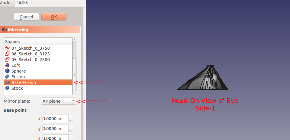
Side-2
With the
Side-1 Base-Fusion Model displayed head-on.
Part Workbench Mirror in XY plane
Draft Workbench Rotate 180 Clockwise
In Path Workbench
Create Job-Side-2
Post Process Lures
Post Process Lure
Generate Side-1 gcode
Generate Side-2 gcode
Adjust both ngc files as needed
Finish Ops
Create Simple Finish Objects
Create Side-1 Finish Job
Use Extrude_Lure as Model
Create Pocket_Shape Op
Create TagDressup/Contour
Generate Side-1Finish gcode
Create Side-2 Finish Job
Use Extrude_Lure (Mirror) as Model
Create Pocket_Shape Op
Create TagDressup/Contour
Generate Side-2 Finish gcode
Move To Mill
Customize gCode
Add custom version control/history
Add custom content
Simulate Milling Operation
Practice Probe of Centerline
Practice Flip and Reset
Create Cutout Paths
From LinuxCNC/Text Editor
Create TagDressup/Contour Cutout
Design to gCode Process Flow
With a collection of nine gcode files the project was moved to the mill. The Probe file was
replaced with a level and a "scribe" point engraver to verify centerline on top. Then
the work stock was flipped and the bottom centerline was verified. Verification of
both top and bottom centerlines involved moving in the X axis along the centerline
and "touching at several points. The combination of the 4-jaw chuck, right angle, level,
centerline, and engraver/probe produced excellent results.
Sequence of Milling Steps:
- Level, Setup Centerline, and Verify
- 089.01_01_016_970_fishlure_waterlineEye.ngc
- 089.02_07_016_495_fishlure_waterlineFinish.ngc
- 089.03_01_016_980_fishlure_flipper.ngc
- Shutdown LinuxCNC and Restart As Is
With Side-2 "now" facing the end mill
- 089.04_01_016_970_fishlure_mirrorEye.ngc
- 089.05_05_016_495_fishlure_mirrorFinish.ngc
- 089.03_01_016_980_fishlure_flipper.ngc
- Shutdown LinuxCNC and Restart As Is
With Side-1 "now" facing the end mill
- 089.07_04_016_999_fishlure_TabContourCutOut.ngc
- 089.08_05_016_999_fishlure_boxCutOut.ngc
Project Photo Gallery:
Click Item to Expand
Through-Wire Wooden Fishing Lure:
Brief Summary of Project:
This project, 021_fishlure, employed previously gained FreeCAD knowledge, experimentation with FreeCAD Parts.Revolve workbench.tool, incorporation of four flute endmills, and cable wrapping loops. The results, lure style 021.4, is a stronger, realistically shaped crank style lure. Fish actually took an interest in this prototype.
Pond testing, lure confirmed the need for a lip. Various lip designs were attempted using materials such as plexiglass and thin sheet metal. Finally a potential, feasible 3D printer
design was discovered. However, that design was determined to be too difficult to insert/mate with the 021.4 style lure body. A modification of that 3D printer design and of the 021.4 style lure was employed. A discussion of the modifications to the lip's 3D design can be found as a "make" of the original lip design. The FreeCAD project 021 was modified to include a pocket cut on the bottom of the lure to support mating with the lip with a modest negative three degree drop. The documents for the 3D printer lip and the pocket cut are provided further below in this section.
Image 11: Realistic Wooden Lure ready for assembly, final expoy coating, hardware, and water trials.


Field Testing
The 021.4 style lure has completed "pond tested".
Prototype:
016.2.1. FreeCad Project 016. Two Flute First Example
021.2.1. FreeCad Project 021. Two Flute First Example
021.4.1. FreeCad Project 021. Four Flute First Example
021.4.2. FreeCad Project 021. Four Flute Second Example
| General Observation
| 016.2.1
| 021.2.1
| 021.4.1
| 021.4.2
|
Responded well to casting
Good distance
Good control even in light wind
Dual trebble hooks played well
Cranking/Playing
Settled evenly in water
Pulled evenly/straight in water
Responded with diving/wiggle
Worked through vegetation
Durability
Sealant/colors held fast
Drag tree branch long surface
Comparable to other crank lures
Classic crank lure shape
Ultra-Light sample
Relative weight to sample
Confirmed need for dive lip
Response From Fish
Hits/Bites
Caught/Landed
Conclusion
Good to fish
Create three more for prototyping
Add dive lips to prototype
Defer Decision
Scale of shape
|
No(1)
Yes
No
Yes
Yes
Yes(2)
Yes
Yes
Yes
Yes
Yes
Yes
Yes
Yes
Yes
No
Yes
No
NA(3)
NA(4)
NA(4)
|
Yes
NA
Yes
No(5)
No(6)
No(7)
Yes
Yes
Yes
Yes
Yes
Yes
Yes
Yes
Yes
No
Yes
Yes
No(4)
No(4)
No(4)
|
Yes
NA
Yes
No(5)
Yes
No(7,9,11)
Yes
Yes
Yes
Yes
Yes
Yes
Yes
Yes
Yes
Yes(8)
Yes
Good2Go
Yes(9)
Good2Go
Yes
|
Yes
NA
Yes
No(5)
Yes
No(7.9.10)
Yes
Yes
Yes
Yes
Yes
Yes
Yes
Yes
Yes
No
Yes
Good2Go
Yes(9)
Good2Go
Yes
|
1. Ballast weights added to lower buoyancy.
2. Responded well with lip added.
3. Added lip since first pond trial.
4. Terminate design development.
5. Too buoyant.
6. Slight yawl/roll as cranked
7. Needs lip.
8. Large mouth bass landed on third cast.
9. Retrofit dive lip.
10. Lip added and pond tested.
11. Lip added and given to associate for testing.
|
Discussion of Process Flow
The FreeCAD project files, resulting gcode, and salient LinuxCNC support files for the Sherline
Next Generation 8580 with Rotary Table/Right Angle are given below in seven part compressed file rar format. A high level view of contents of the compressed files is given directly below. Links in the next section lead to the downloadable seven compressed files.
- A file called dirlist which provides a working manifest of the zip file.
- Folder containing a more detailed a working checklist for moving through the milling process.
- FreeCAD project files for Lure and Finish Operations.
- The full collection of gcode for milling the
lure objects.
- A folder containing supporting program modules with images which require loading to the LinuxCNC machine folders.
- The Cura 3D printer design project and gcode are available from the lucca82 Make Project at Thingiverse. That site also contains a discussion directly related to the 3D Printer aspect of the lip for the lure.
Download Actifcats
- Part1
- Part2
- Part3
- Part4
- Part5
- Part6
- Part7
gCode For Lure Milling:
gCode
Filename
| Purpose
| Comment<
|
| 081.15_07_009_980_fishlure_probe.ngc |
Execute a probe along centerline |
Performed manually. |
| 089.03_02_016_980_fishlure_flipper.ngc |
Flip workstock from 0 to 180 degrees |
Executed well |
| 089.06_02_009_980_fishlure_reset.ngc |
Flip workstock from 180 to 0 degrees |
Executed well |
| 092.01_06_021_973_057_ure_SideA_Top.ngc |
Executes waterline surface milling of SideA |
Executed well |
| 092.02_06_021_973_057_lure_SideB_SplitFace.ngc |
Executes SideB milling for through wire placement |
Performed manually. |
| 092.03_04_021_973_057_lure_SideB_Bottom.ngc |
Executes waterline surfacemilling of SideB |
Executed well |
| 092.04_06_021_973_057_PinHoleOnly_lure_SideB_SplitFace.ngc |
Drills Pin Holes for SideB |
Performed manually. |
| 092.99_05_021_973_057_outline_lure_SideB_Bottom.ngc |
Creates trace outline of SideBfor lip alignment |
Executed well |
| 100.01_08_031_973_057_lipCut3dPocket_boxCheck.ngc |
Executes the pocket cut for lip |
Executed well |
gCode Filename syntax
ggg.ss_vv_fff_ppp_xxx
ggg: Identifier for gcode folder/family repository
ss: Identifier for gcode within a folder/family
vv: Revision numeric
fff: FreeCAD project workspace
ppp: Project within a FreeCAD project workspace
xxx: Identifier assigned to a hybrid of a Project
|
|
|
Tool Table Entries
- T21 P21 Z1.273 D0.045 ;dremel scribe engraver added 20190502
- T22 P22 Z4.013 D0.0625 ;dremel 1/16 drill
- T23 P22 Z4.013 D0.0725 ;dremel 3/32 drill
- T24 P24 Z2.264 D0.1275 ;1/8 x 3/8 4flute
- T25 P25 Z0.0 D0.25; 1/4 x 38 2 Flute End Mill Hand Powered
"stepper.var" Entries
5220 1.000000
5221 0.000000
5222 -0.605000
5223 -2.000000
5224 0.000000
5224 0.000000
Discussion of Design Process Flow
See the earlier crank lure and
realistic lure for a discussion of the maturing steps in crank lure design. Instead of using a Side-1 and
Side-2 (Right Half and Left Half) the perspective was changed to Dorsal {Top} Half and Belly {Bottom} Half.
This change allows the compartmentalization of the design. The Dorsal Half has both eye buds and the primary
shape of the lure. The Belly (Bottom} Half features include the Through Wire, the Belly Hook Loop Wire,
and Alignment Pins Holes.
Dorsal Half/Belly Half:
The initial steps in the design differed from the earlier crank lure of Project 016. The Dorsal or Top Side
was based upon an ellipse 2D shape. Using this shape as the outline, a continuous multipoint DraftWire 2D line
was drafted from the left most point touching the x-axis to its right most point touching the x-axis. Using the
Draft bench-revolve, the 3D Dorsal Half was created. With the Dorsal Half defined, it was then copied/pasted as
the Belly Half. With the Belly Half shape now available, the Belly Half was modified from within the Draft
workbench to generate the "desired" shape.
From that point forward the Dorsal Half and Belly Half were available for creation of Jobs and the associated
*.ngc code. The Through Wire Processing was originally attempted as a separate CAD/CAM CNC gcode process. But
common sense that it was better to create the Through Wire grooves, drill Belly Holes, Alignment Holes, "custom
fit" craving of gaps for wire wraps manually, and adding a pocket cut to provide mating surfaces with the plastic lip. NOTE: For this early prototyping of the 021.4 style lure, the pocket cut was executed post-bandsaw separation because the need for the lip had not been confirmed. The difficulty in the alignment curved body lures presented with this deferred pocket cutting of the prototype strongly suggested that this pocket needs to be cut prior to the waterline surfacing while the centerline and factory edges of the woodstock can be employed.
A bandsaw was employed to separate the Dorsal Half and Belly Half from the workstock. The Dorsal Half and the Belly
Half were then placed in a vise (with sacrifice wooden bumpers) to allow the drilling of the two alignment holes. The
original centerlines (now significantly shortened) of the Dorsal Half were used for the drill operation setup.
Once the Alignment Pin Holes had been completed the two halfs were separated and then re-assembled. During the
re-assembly, the Belly Half was now placed above the Dorsal Half such that the Alignment Pins could be inserted to
allow exposure of the Belly Half's split face matching surface. With the Belly Half's matching surface exposed its
centerline could be roughly verified between the head and tail points along the x-axis. The lures Through Wire
groove was then scribe to a sufficient depth to allow the wire to just reach the top of the surface. The Belly Hook
hole and its associated wrap "bore" hole were drilled. The accompanying "howto zip package" will provide a more detail set of steps as well as the pocket cut gcode and additional files to support this new operation.
The two lure halves were removed from the vise. The Through Wire Loops and Belly Hook Loops were created, assembled,
and installed. Clearance "bore" holes were identified and created as needed to allow a "good" fit between the two
halvs. This required a couple of assembly attempts using the Alignment Pins and then gently separating. During
separation the both halves were examined to locate any points of conflict that might require additional "boring/cutting".
Once a "good" fit was achieved with the two halves and alignment pins were epoxied bonded. The excess lengths of the
alignment pins were allowed to protrude from the Belly Half while being tangent with the Dorsal Half's surface. Painting
coats were added as each dried. Avoid placing paint on the lip mating surface of the lure. Once the lure has dried the lip is ready to be epoxied into place. After that mating joint has cured a slanted slightly off-centerline pre-drill hole should be made such that the lip is pulled toward the mating surfaces of the lure. A small wood screw should then be fully inserted and then sealed. The body of the lure, immediate mating of the lip, and the lip's screw should then be receive sealant coat. The lure hardware was added after a "full" sealant cure in a solar oven.
Dorsal Half
Begin with the Draft Workbench
Create a Construction group
Within the new group create
ellipse
Use the ellipse's Major/Minor Radius(from the Model)
Use Draft.Draft To Sketch to create a
sketch version of this figure.
Take advantage of undocumented
feature/bug and ignore
non-constrained layers
From the Part Design Workbench
Create a New Body called "TopHalf"
From the Part Workbench
Add the Dorsal Half solid to this new Body
Create sphere and place it as the right eye of the lure.
Create sphere and place it as the left eye of the lure.
Fusion of the lure/eyes as a Model.
From the Path Workbench
Create a Job Dorsal Half
Use Fusion as Model
Setup Stock/Tool
Use Waterline
Set start depth at 0.0 inch
Set final depth as needed.
Set parameters as needed
Select Waterline Operation
Note that the Project 021 uses either Four Flute
End Mill for milling the surface.
Setup Contour Operation
Setup Dressup Tags Operation
Belly Half
Begin with the Draft Workbench
Use the existing Construction group
Paste this sketch
Rename this sketch for use on the BellyHalf
Double click this sketch to invoke the Sketch Workbench
Modify outline sketch to suit.
Drag it a little and place in a new position.
Then grab and drag the next point.
From the Part Design Workbench
Create a New Body called "BottomHalf"
From the Part Workbench
Add the Belly Half solid to this new Body
From the Path Workbench
Create a Job BellyHalf
Use Belly Half solid as Model
Setup Stock/Tool
Use Waterline Operation
Set start depth at 0.0 inch
Set final depth as needed.
Set parameters as needed
Select Waterline Operation
Note that the Project 021 uses either Four Flute
End Mill for milling the surface.
Setup Contour Operation
Setup Dressup Tags Operation
Lip Pocket Cut
Begin with the Part Workbench
Convert Lip STL model to a Mesh model.
Convert Lip STL Mesh model to a Solid.
Use the Previously create belly bottom
From the Draft Workbench
Create the Actual Cut Pocket Model
From the Part Workbench
Continue development of the Actual Pocket Cut Model
Encase the cut model in a workstock block suitable to reflect
From the Job Workbench
Create a Job using the Pocket Cut Model as the Job's model
Under Operations Select 3D Pockets
For Depths Start Depth
select default and set
later. Set Finish and Step Down to suit.
For Heights and Operation select select the best for your equipment.
From the Combo View select the 3D Pocket operation
Once entered FreeCAD will begin a round of calculations
Post Process Lure
Generate Dorsal Half gcode
Generate Belly Half gcode
Generate Belly Outline gcode
From a text editor import a copy of the Belly Half gcode
Delete all Dressup and Surface gcode except for the last waterfall loop.
For the identified last waterfall loop perform a global Z
replacement such that Z now has a minimal depth
cut. For example Z=-0.01 in.
Save this document as the Belly Outline gcode.
Generate Lip Pocket Cut gcode
Adjust both ngc files as needed
Customize gCode
Add custom version control/history
Add custom content
Simulate Milling Operation
Practice Flip and Reset
Simulate Dorsal Half Waterline and Contour/Dressup
Simulate Belly Half Waterline and Contour/Dressup
Simulate Belly Outline and Lip Pocket Cut
Design to gCode Process Flow
With a collection of nine gcode files the project was moved to the mill. The Probe file was
replaced with a level and a "scribe" point engraver to verify centerline on top. Then
the work stock was flipped and the bottom centerline was verified. Verifcation of
both top and bottom centerlines involved moving in the X axis along the centerline
and "touching at several points. The combination of the 4-jaw chuck, right angle, level,
centerline, and engraver/probe produced excellent results.
For a detailed, stepwise description of "how-to" create the lure from the CNC
Mill to painting/coating and lip assembly view the process steps"how-to" document.
Project Photo Gallery:
Click Item to Expand
NOTICE: This site was fabricated for best viewing using
Netscape 4.x, or a functionally
equivalent browser.
Please send comments or questions using e-mail, voice telephone at 919-846-7705. (Last update: October 10, 2019 tar)

