Retail Version:


Brief Summary of Project:
This project did not involve any special CAD/CAM/CNC knowledge. The design concept was borrowed from a similar fishing lure mobile that was
seen at a cafe/garden shop. The cafe version was selling for over $80. Hanging on display it was about 36 to 48 inches long. It had about
eight/ten large lures with their hooks. Separating each lure was a piece of wood. The wood varied in quality from ink pen blank to "rough-hewn".
The cable used to suspend the various lures and wooden pieces was large with correspongingly large metal cable clamps. Both the cable and
clamps exhibited a light rust pinta. The lures appeared to be squashed between the piece of wood. The retailer did not back-off the price.
Retail Version:
The "borrowed" design concept has been executed twice now as gifts. This proved to be a good activity for
involving the wife: wood, colors, beads, lure arrangement, etc. This version of the borrowed design concept has a shorter suspension length.
The hole for threading the cable through the lures were located individually at the "balance spot" of each lure. As such the lures
are positioned on the cable without yawl or twisting about their dorsal axis. The center holes for wooden pieces were located
at the geometric center of the top face of each piece. Between each lure and piece of wood there is a bead that improves articulation
of the assembly. A heavy duty salt water swivel was added to allow additional articulation at the top loop of the cable. Finally at
the bottom loop of cable, an appropriate spinner lure was added for additional color and "bling".
Fishing Lure Mobile: Balance, drilling, layout, assembled.


Parts List:
| Part | Quantity | Subtotal | Source | Part Detail Description |
|
Cable
Clamps Lures Beads Spacers Swivel |
3 Ft
1 Kit 6/Buy 1 Pack 10/Bundle 1 |
$ 0.78
$ 1.28 $12.00 $ 3.06 $24.60 $ 0.00 |
Lowes
Lowes Flea Market Hobby Lobby Wood- craft On-Hand |
Blue Hawk 1/16 in Weldless Galvanized Steel Cable
Diameter 0.062 inch
Safe Working Load 96 lbs
Color/Finish Family Silver
#348161
Fresh Water Lures
Used
Less Hooks
Wooden Ink Pen Blanks
Bundle pricing
Various type.
Matched to size
|
Discussion of Process Flow
This project was designed, kitted, milled, and assembled on-the-fly. The equipment and tools listed below could have been
replaced by any array of power and/or hand tools. The process steps listed further below are a good rendering of the actions
taken to create the project.
With the exception of purchasing slightly exotic woods, this project was executed "on the cheap".
The real challenges were:
Equipment/Tools
Shop Equipment:
Process Steps:
The project was executed in the following stepwise manner
Brief Summary of Project:
The intent was to create suitable wooden puzzle box as a specific gift. The project involve creating matching puzzle
box components with interlocking dovetail slots/tabs. This variant of prior wooden boxes required additional CAD skill and on-the-fly design changes at milling.
The major project break came from rotating the design center line 45 degrees. The design manufacturibility feasibility was verifeid
simulation runs on a standalone LinuxCNC PC and then using scrap material on a Sherline 8580 NexGen controlled by LinuxCNC 2.8.


Discussion of Process Flow
The development of the puzzle box involved a couple of false starts, going down various rabbit holes, using spikes as needed, employing maturing iterations during the design process, and more than a few scrap runs at the CNC bench. The PuzzleBox desgin was rendered using FreeCAD. The desgin was executed in builder's grade yellow pine using Sherline 8580 NexGen running under LinuxCNC/Ubtunu. A short period of sanding, surface preparation, and staining yielded a Rosewood stained Puzzlebox. The presentation of the Puzzlebox as a gift was well received.
The first false start involved FreeCAD 19. This version of FreeCad proved to be unusable as installed. The FreeCAD 19 installation required a complete restoratiion of the system backup image (Clonezilla). Special thanks go to Mark Ganson for his efforts to introduce me to FreeCAD 19 and the Dovetail Design desing feature it offers. Time constraints and my uncertainity of using the feature forced abandoment of this effort.
Upon restoring FreeCAD 18.4 the focus was on creating the bottom of the puzzlebox object first. Early in the design process it became obvious the desgin simplification that could be derived from translating the design (bottom and lid) 45 degrees. This allowed for changing one dimension at a time as one moved along the centerline or above/below.
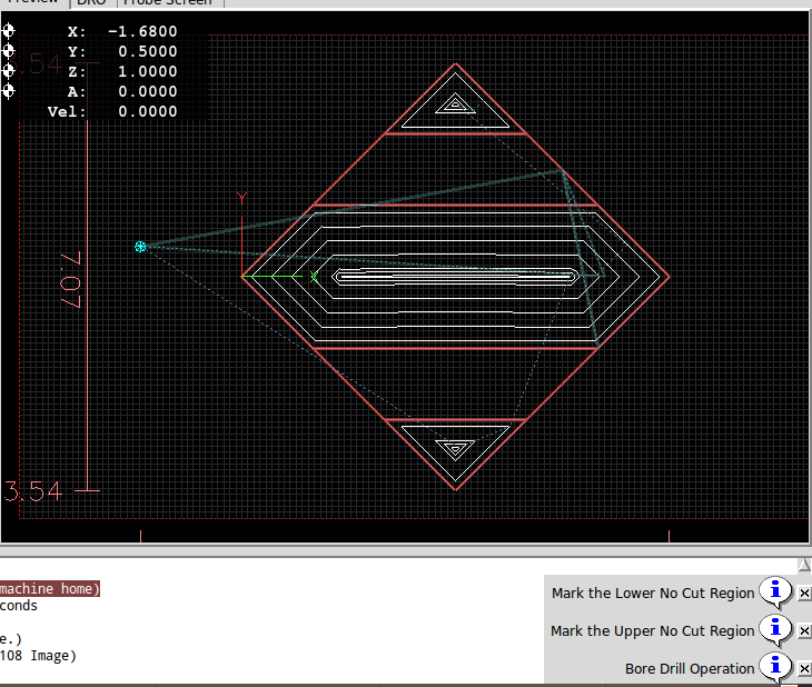
Once the bottom design of the puzzlebox was achieved the matching puzzlebox lid was created mirroring the surface features of the bottom. At this point there was no attempt to generate dovetail cuts for the slots or tab. Instead the effort centered on identifying cut regions and no cut regions for the bottom and the lid. The concept was to specify first the major milling cuts on the bottom and create the associated toolpath gcode. Then the dovetail cuts for the the bottom and lid would be sepcified. This portion of the FreeCAD project desgin data was captured in the corresponding spreadsheet. As the design evolved the decision was made to put the locking mechnaism (locking pin, strong magnetic material, the locking mechnism hole) on the Lid at one end of the Lid's center slot along the Lid's centerline.
Two "raw" Job tasks outputs were derived from the FreeCAD Phase of the project. These two bodies of gcode were then split into two sets of gcode programs. Each gcode program had a suitable header added, various variables defiend, o-code inserted, substituted variables, adjusted for tooling difference between FreeCAD and the LinuxCNC tooltables, and added LinuxCNC specifc syntax.
FreeCAD 18.04 does not exactly provide features/tasks for creating the long slots and tabs that the puzzlebox required. It does provide the capability to generate gcode outputs that support creation of outlines/boundaries and the creation of channel cleanouts (pockets) that will accommodate the slot/tab features of the puzzlebox.
Both the slot and tab features of the puzzlebox are composed of a long dovetail cut and a channel cleanout. These sequence of development and production followed gcode for Object Outline with Cut/No-Cut Regions, gcode for four Dovetail Cuts, and for Channel Cleanout. FreeCAD design rendered outputs yielded a collection of gcode for the Object Outlines and for the Channel Cleanouts. The FreeCAD spreadsheet for the project also provided a library of data for the manual development of the eight Dovetail Cuts (four each for Bottom and Lid).
LinuxCNC provides three sets of syntax that supported the gcode generation. The first set of syntax was the standard gcode . The next set of syntax provided was o-code. The final set of syntax is composed of user defined programs referenced as m-code (100-199).
The suggested sequence/order of milling to use in the CAM phase of the project is given in the following two sets of gcode.
| gcode File | Tool | Purpose | Comments |
|
Gcode For Puzzlebox Bottom | Use Home and Check Holes to verify before starting | ||
| s001_02_104.01c_02_179.983_038_outline_boxBottom.ngc | Dremel Scribe | Displays cut and no cut regions for bottom and slots. | Abort at anytime confidence is reached. |
| s002_03_104.03_26_038_dovetail_slot_bevel_single.ngc | Dovetail Cutter | Forms dovetail groove of slot | Creates four bevels |
| s003_01_104.01_04_179.983_038_boxBottom .ngc | 1/4 inch longshaft tool | Executes the mill cutting tasks for slots and cylinder. | Provide "rough" mate for lid's "pin-key" |
| s004_04_104.01_03_179.984_038_contours.ngc | 1/4 inch longshaft tool | Cuts tags and contours for bottom. | Same toolpath as used on Lid. If issues arise use a bandsaw with high tpi. |
| Gcode For Puzzlebox Lid | Use Home and Check holes to verify before starting | ||
| s005_03_104.02c_02_179_985_outline_lid.ngc | Dremel Scribe | Marks the cut/no-cut regions of the lid and outline | Abort at anytime confidence is reached. |
| s006_06_104.04_19_038_dovetail_tab_bevel.ngc | Dovetail Cutter | Forms dovetail shape of the tab | Creates four bevels. |
| s007_07_104_038_179_982_lid.ngc | 1/4 inch longshaft tool | Executes the mill cutting tasks for tabs, cylinder, and lock. | Creates "pin-key" hole |
|
s008_01_104.01_03_179.984_038_contours.ngc | 1/4 inch longshaft tool | Cuts tags and contours for lid. | Same toolpath as used on bottom. If issues arise use a bandsaw with high tpi. |
For a level of confidence that "all is well", properly Home-d, and running without issues "Check Holes" were created and readily used to
test the validity of CNC control. This is not a requirement, but a best practice in AAP's shop. Test holes were created immediately after
the first, original setting and verification of "HOME". Suggested Check Holes' dimensions are provided further below. Drop back tp testing
the currently active tool as often as deemed neccessary. One of the best "decision points" is the "Abort or Continue" dialogue. That
dialogue window provides enough time to think, decide, and abort to test.
Dremel Scribe Engraver
 MDI Tabsheet Commands
 One of various possible jogging devices/approaches.

Puzzle Box Design Supporting Artifacts
Tool Table Entries Tool and Pocket identifiers are those defined by the toolable used by the LinuxCNC based CNC (simulator and Sherline 8580 NexGen). Corresponding gcode and tooltable modifications are required to conform to each unique CAD/CAM setup.
| General Knowledge | Design | Simulation | Project |
|
45 Degree Triangle 
30-60 Degree Trianlge 
Layout for Dovetail Cuts 
LinuxCNC Setup Add Lines to *.ini 
Add Files to Folders 
Dialogue Messages Verify Location 
Verify Readiness to "GO" 
Shop Support 
|
FreeCAD 18.04 Spreadsheet 
Bottom 
Lid 
Jobs to gCode 


|
Puzzle Bottom s001_*.ngc Outline Start-- Stop 

s002_*.ngc Bevel Cuts ---- First Cut 

More First Cut Testing 

Bevel Cuts For Record 


Cleanout of Channel 

s003_*.ngc Cylinder + Drill Cuts 


s004_*.ngc Contour + Tags 

Puzzle Lid s005_*.ngc Outline 
s006_*.ngc Bevel Dovetails Cuts 
s007_*.ngc Cleanout + Drill 


s008_*.ngc Contour and Tags 

|
Finished Puzzlebox
Display Puzzlebox 

Test Bottom - Lid 

Test Runs for Lid 

Almost Good Lid 


Check Holes Move To Test Hole

Not Used 
|