
| Link | Comment |
|---|---|
|
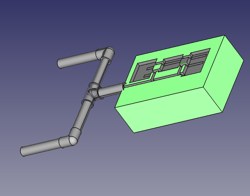
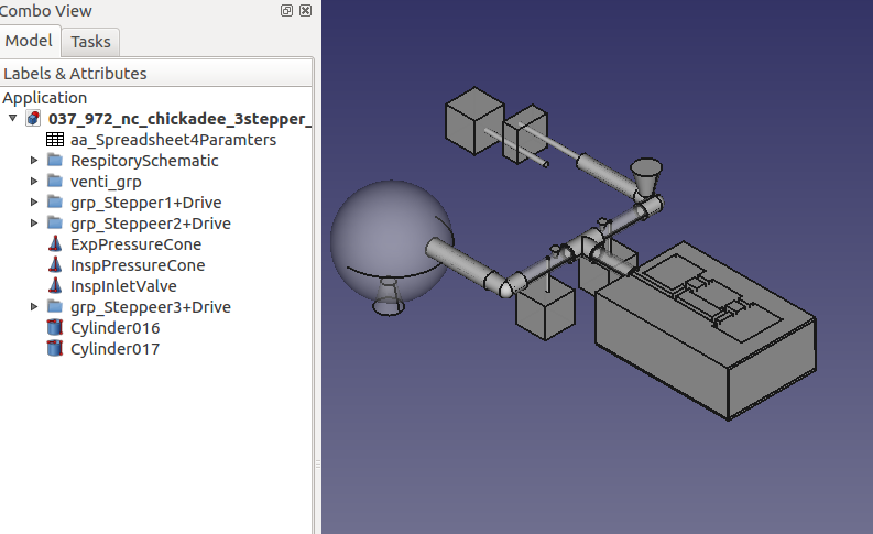
FreeCAD was used to generate the "test lung schematic" in 3D. It was also used to render a 3D depiciton of the mechancical asssembly of the envisioned stepper motors, drive mechanism, valves, pressure gauges, inlet and purge ports, etc. It also served as the tool for visualizing the conversion of milling operations into a piston stroke amd opening/closing valves. |
|
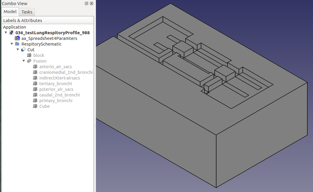
A rendering of the "test lung" schematic is based on rendering by Robert Lasiewski.
The FreeCAD files, 036_testLungRespitoryProfile_987.FCStd and 036_testLungRespitoryProfile_987.FCStd1, are availale from the project bundel found at GITHUB, https://github.com/trooker/a034_nc_chickade. |
|
The FreeCAD files, 037_972_nc_chickadee_3stepper_working.FCStd and 037_972_nc_chickadee_3stepper_working.FCStd1, are availale from the project bundel found at GITHUB, https://github.com/trooker/a034_nc_chickade. |
|
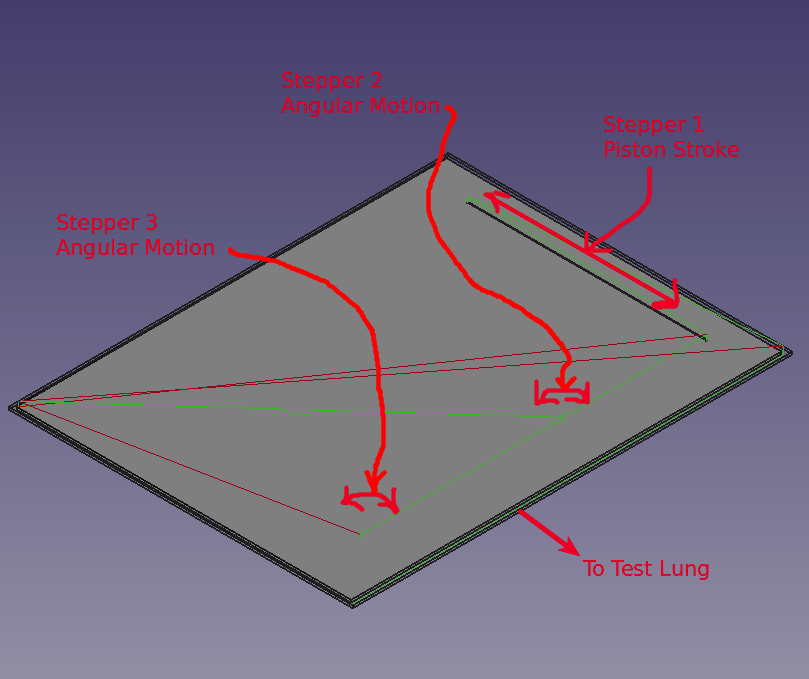
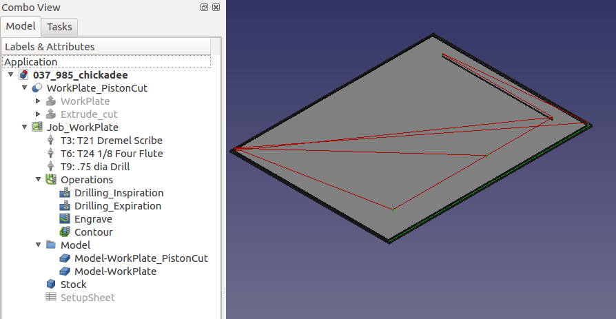
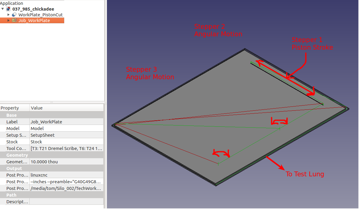
Evolution of the workplate from the original 3D milling operations.
The FreeCAD files, 037_985_chickadee.FCStd and 037_985_chickadee.FCStd1, are availale from the project bundel found at GITHUB, https://github.com/trooker/a034_nc_chickade. |
|
A piston approach was taken as a good means for insuring the proper volume of the Tidal Volume by presicion stepper control of the height of a cylinder of air. The inspiration values and expiration values would address the inspiration/expiration ratio. The breaths per minute would be a function of the steppers' linear and angular movement as well as Arduino processing time. |
|
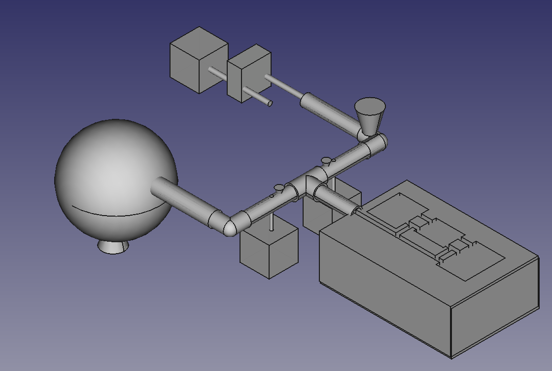
The top view displays the proposed ventilator simulator with a rendering of the static schematic of the lungs as authored by Robert Lasiewski . The discussion presented in that source should be reviewed early in any effort to understand the complexity of respiration. |
|
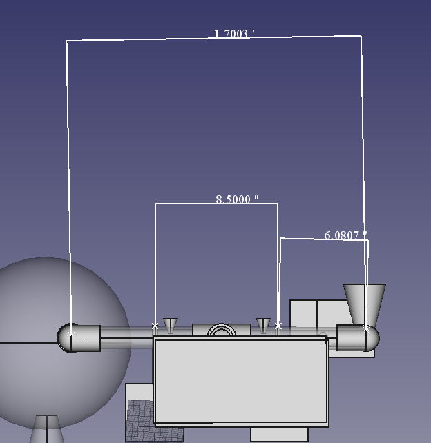
Frontal view with rough dimensions depicted. |
|
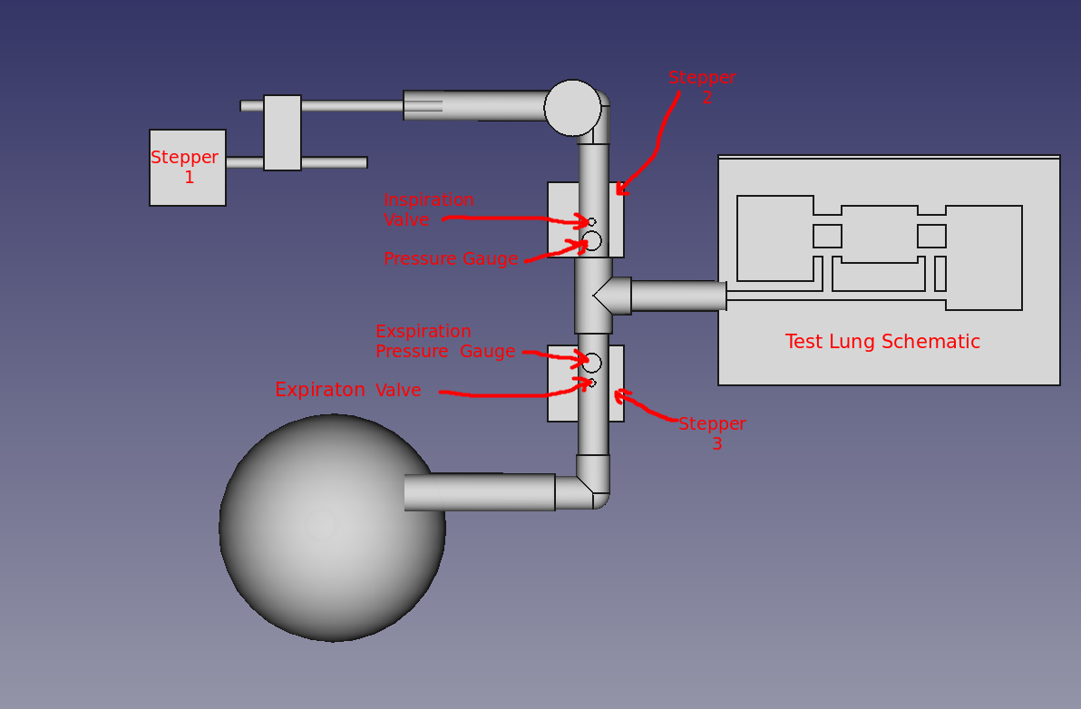
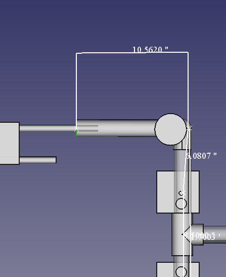
Top view focusing on the saddle, psiton, inlet port valve, stepper 2, the inspiration valve, and pressure gauge. The dimension display provide further enlightenment concenring the physical characteristics of the ventilator simulator. |
|
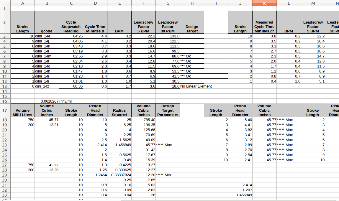
Early stepper motor testing as a CNC and number cunching drew concern to stepper speed, piston stroke length, and volume pushed/pulled by the psiton. |
|
Fine tunning of the piston diameter and piston stroke length suggested a "workable" value for use in the X axis direction. |
|
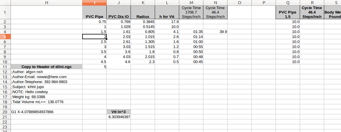
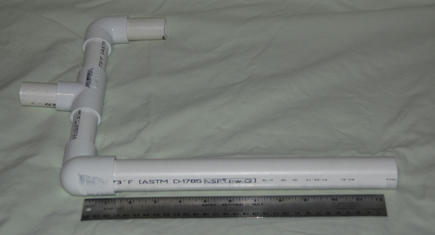
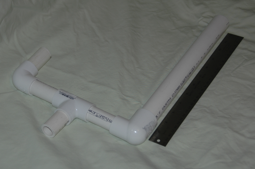
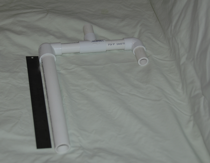
Basic PVC plumbing 1 inch and 3/4 inch diameter.
Front view showing portal to test lung (3/4 inch dia.). Rear view from piston and exhaust reservior (1 inch dia and 3/4 inch dia., respectively). |
|
|
|
|
With the basic plumbing established for the ventilator simulator, the next phase in the mechanical design was to describe a set of CNC milling operations that would drive a linear piston for a specificed distance and open/close airflow control valves with precision. This set of milling operations would then be submitted to FreeCaad's Path module for processing into collection gcode statements. This collection forms the "toolpaths" that the CNC milling machine will follow. |
|
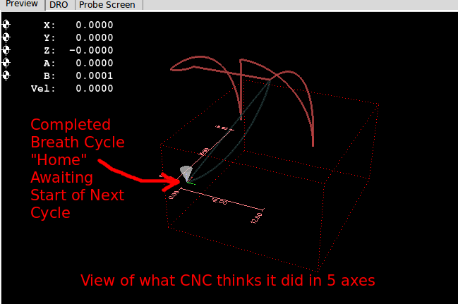
Early rendering of the FreeCad produced gcode displaying the XYZAB five axes complexity. |

|
The current evolution of the dilni.ngc yields a simple set of angular movement at the start/end points of the pull/push stroke of the ventilators simulator's piston. The set of angular movement close/open the appropriate expiration/inspiration valuse.
At present the inlet portal valve, exhaust purge valve, and the expiration/inspiration pressure gauges have not been incorporated. With the present Arduino Adafruit AMS shields a four stepper could be added as Stepper C for an additonal angular movement control. |
|
The video depcits the significant reduction in the complexity of movement and control that were achieved. |