Top Level Working Performance Criteria
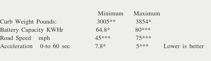
Note: *: Source information provided by Car Buzz webpage.
Note: **: VW New Beetle 2006 Owner's Manual
Note: ***: Author's preferred values.

This web page contains an overview, subsections detailing of the project's major pieces, and the evolving/moving goaline.
The following outline is presented to facilitate the reader search of the details:
As originally planned the project began with an assessment of available technology in an effort to determine a likely path forward to replacing the heavy and expensive lithium-ion batteries. Eventually the assessment sought to identify techniques for placing electrons in a a containment pool in such a manner that the containment pool could be recharged or hot-swapped to provide a refueling strategy. One of the most promising approaches involved Floating Gate MOSFET. The semiconductor industry has agressively push varoious size memeory FGMOSFET devices into the world consumer market. Twisting and redefining the FGMOSFET just a little might result in a device which awaits a command to place electrons in a floating gate (charge mode), awaits a command to report voltage l evel (read mode), awaits a command to erase (discharge mode), or awaits final degradation over the life of the FGMOSFET ( estiamted at 10 years).
The bulk of the technology study during this project centered on preliminary reference work, QUCS, project artifacts collected in a repositry at github, and Cullinan's work product supporting his January 2015 doctorial thesis. This preliminary reference work split into artifacts of critical importantance termed "Primary References". A second order contribution of lesser importance to the technology study was collected and termed "Supporting References". A set of images, downloaded artifacts, and work notes was also collect. This colletion of working papers is available upon request which can be made using the email form at the bottom of this web page.
The technology study used a 'funnel' strategy. It started with a broad, wide open look at ground modile power sources. It quickly ventured to electric fields and electron/quantum level behavior. Shortly, it began to fucus on 3D VNAND memory as a potetnial answer. Subsequent probing discovered a vast array of helpful, menaingful technical artifacts.
The first steps after discovering that a solution similar to 'a 3D VNAND memory style power source device' might work was
attempting to derive an estimate of how much electrical power the current electric vehicles, EV's, required to be market-ready. After actually test driving a
number of EV's and reviewing marketing literature, it was assumed that something closely matching the Kia Niro EV should be
the essential acceptance criteria.
Top Level Working Performance Criteria
Note: *: Source information provided by Car Buzz webpage.
Note: **: VW New Beetle 2006 Owner's Manual
Note: ***: Author's preferred values.
At this point in the technology study a working cost estimate was generated to reflect knowledge gained regrading conversion of a diesel 2006 New Beetle to an electric vehicle and the cost of ownership of a 2022 Kia Niro EV6. The cost estimate was in the form of spreadsheet analysis. Ths spreadsheet analysis only served to highlight the criticality of the power source component.
Shortly after reaching this junction the 'essential technical' sources were discovered. These sources split into two realms:
The specific version of FreeCAD employed was 0.18.4 with the A2plus v04.49.
Shortly after starting "to make virtual sawdust" if became apparent that this maturity and CAD tooling a massive VNAND strucutre was not going to happen. As such decision was made to limit the VNAND model to a straight four cell string. That decision allowed the creation of string that could later be "meshed" in a multi-dimenstional array of strings. But first we had to 'learn how to walk' or control the individual cells. The decomposition strategy is reiterated for emphasis:
Coupled with the FreeCAD development of a Floating Gate Electron Reservoir Power Source model was a spreadsheet analysis that attempted to predict the electron capacity that the power source should exhibit. It numerically showed the substantial quantity of elcetrons that a 64.8 to 80 KWHr power source would need to store and manage.
The spreedsheet analysis also pulled together the voltage levels required to prompt the desired charge, discharge, and return-voltage-level behavior of the assembly. These voltage level inputs served as inputs to the basic VNAND assembly. What exactly occurred in the VNAND assembly remained a 'black-box' until the next piece of the project, the QUCS piece began to pursure it.
The FreeCAD artifacts and the associated spreadsheet analysis artifact reside the GITHUB respository, URL**: https://github.com/trooker/Floating-Gate-Electron-Reservoir). The project is listed as private. Access can be obtained upon request via the email form given at the bottom of this webpage.
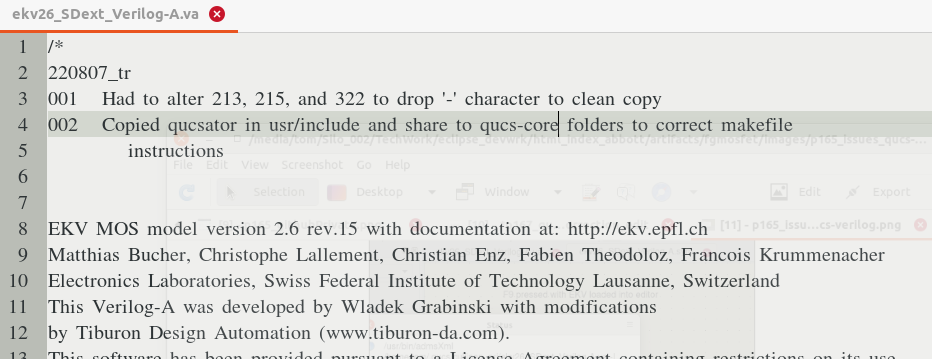
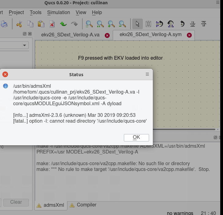
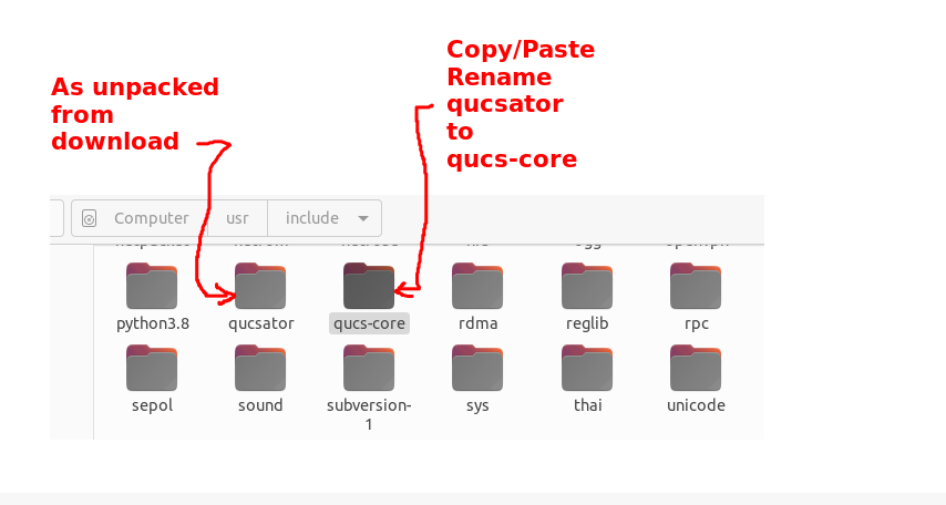
The specific version of QUCS used was v0.0.20. The 'verilog-a-devices' collection of components was added per M. Cullinan's thesis. The only major hickup in installing the QUCS and 'verilog-a-devices' collect was that the verilog build script had three issues that need to be resovled. First the script file ekv26_SDext_Verilog-A.va needed three minor edits. The next complier run produced an error messages which indicated that the qucs-core/file was missing. Subsequent troubleshooting discovered that the required file was located in the qucsator folder. This was resolved by a copy/paste/rename of the qucsator folder to qucs-core. All ran well after these four changes.
Rapid progress down the steep learning curve began once the Verilog family of components was available in the component collection. The Verilog collection of components contains the esstenial EKV2.6 nmos device. A set of 'spikes' (or learning projects) was used to travel down the learning curve have been include in the bundle of QUCS projects sent to the GitHub project repository. By the time the four simulation simulation environment had been successfully negoiated a comfort level in usage of QUCS had been acquired.
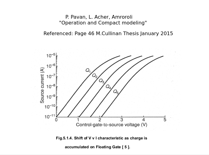
It was at this junction that M. Cullinan's 2015 thesis began to add value to the Floating Gate Electron Reservoir Power Source project. The largest contribution of M. Cullinan's thesis was the mention of the Quite Universal Circuit Simulator, QUCS, mentioned earlier in this project thread. Without the QUCS simulator the FreeCAD work product would merely be an annimation tool demonstrating high level control without quantitifying the charge stored or released. The whole thesis was eye-opening. His introdcution compact Equation Defined Devices was extremely helpful. His derivation of floating gate charge accumulation in Chapter 3 of his thesis was another prime reason for following his steps. M. Cullinan reference (figure 5.1.4) to P. Pavan, L. Acher, Amroroli "Operation and Compact modeling" artifacts provided another key nail in moving this project further.
The exploritory path of the Floating Gate Electron Reservoir Power Source (FGERPS) project mirrored to a very large extend the evolution of M. Cullinan's thesis development replicating the FGMOSFET model/symbol (figure 8.1.2) and four simulation test envrionment (figures 5.1.1a, figure 8.1.1, figure 7.5.1a, and 7.6.1). QUCS artifacts associated with the model and simulation test environments are available at https://github.com/trooker/Floating-Gate-Electron-Reservoir. The project GITHUB repository is currently set to private. Access can be requested using the email given at the bottom of this page. Once confidence was gained in the model and the results from testing in the simulation environments was obtained, the project began to explore the realm of Floating Gate charge accumulation. The resulting models/equations are avialable from https://github.com/trooker/Floating-Gate-Electron-Reservoir.
As of 5/4/2026
The six key schematics/models of the FGERPS project have been updated to reflect the just released User Library specific to the AAP project. All six have been submitted for vigorous testing under QUCS simulator and yielded favorable results. These artifacts will be used to update the current contents of the project held in the private repository on GITHUB. FGERPS can now perform charge, discharge, and read/monitor functions.
| Model Parameters | Function/Model/Equation |
|---|---|
|
height=133.2078,
center=20.26626, location=-234.5016, shape=127.9543 |
= height * (1-exp( - ( (x - location) / (center-location) )^shape) ) |
| Parameter values derived from best fit of simulation data 8.3.1.3 for Floating Gate Voltage after pulse fall (volts) |
where:
exp represents exponential function x represents the independent variable Vtun |
| Model Parameters | Function/Model/Equation |
|---|---|
|
height=1350,
center=11.74718, location=8.90427, shape=6.605582 |
= height * (1-exp( - ( (x - location) / (center-location) )^shape) ) |
| Parameter values derived from best fit of simulation data 8.3.1.4 for Itun at start of pulse(A xe-9) |
where:
exp represents exponential function x represents the independent variable Vtun |
| Model Parameters | Function/Model/Equation |
|---|---|
|
height=133.2078,
center=20.26626, location=-234.5016, shape=127.9543 |
= height * (1-exp( - ( (x - location) / (center-location) )^shape) ) |
| Parameter values derived from best fit of simulation data 8.3.1.6 for Is at end of pulse just before fall (A xE-5) |
where:
exp represents exponential function x represents the independent variable Vtun |
The question being pursude now is what quantity of charge can a 'basic cell' of the Floating Gate Electron Reservoir Power Source obtain. Using the "basic cell" as the building block, then the primitive four cell string and eventually the various VNAND achitecture strageties will be explored in the quest for a 64.8 to 80 KWHr power source platform.
A request for status update can be submitted using the email form given at the bottom of this page.