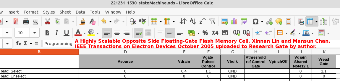
| Image | Comment |
|---|---|
Charging (FN)
Discharging (IHEI) 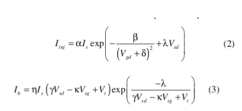
|
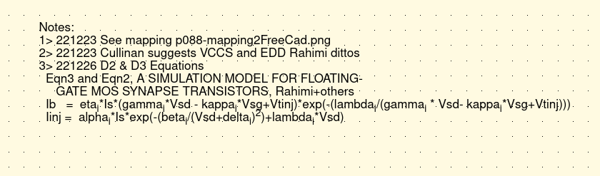
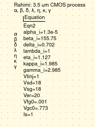
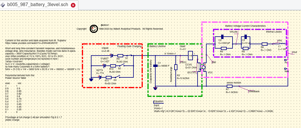
The Rahimia team's technical paper "A SIMULATION MODEL FOR FLOATING-GATE MOS
SYNAPSE TRANSISTORS (page 2) published through the University of Washington provides a simulation model for the 3.5 um
CMOS process. The model is a grwoth in complexity from the Cullinan Thesis model introduced earlier. The
Rahimi team simulation model address both charging and discharging modes.
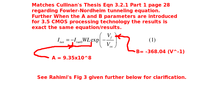
FN: Charging The Fowler-Nordhiem parametrs provided in the Cullinan thesis closely matchs those of the Rahimi abstract. As such the Rahimi parameters shown should be fairly close for this iterration and maturity of design for the Floating Gate Electron Reservoir Power Source. The Rahimi presentation clearly states that the FN tunneling process removes electrons by means from the gate. IHEI: Discharging The IHEI, impact-ionized hot-electron injection, equations and parameters were derived from emperical work by the Rahimi team. The IHEI process as described by the Rahimi's article adds electrons to the floating gate. |
|
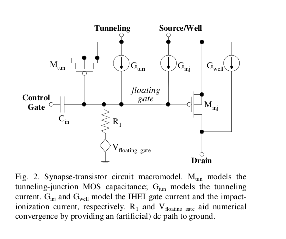
Ibid.Fig 2 of the Rahimi team's presentation shows the model rendered as a tunneling entity on the left and an injection entity on the right. The two process entities are coupled together via the floating gate. The Floating Gate Electron Reservoir Power Source simulation model discharging mode owes a great deal to the Rahimi effort. |
|
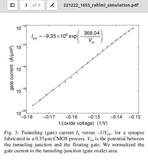
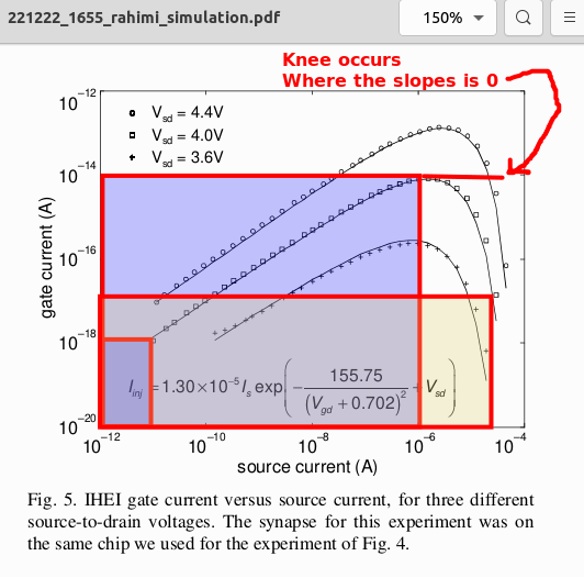
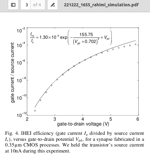
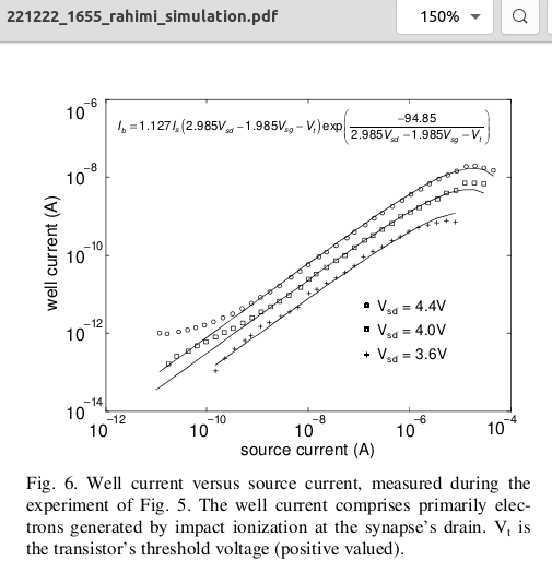
Ibid. Rahimi Fig 3,4, 5, and 6 page 3 presents a set of resulting simulation plots showing the proceeds of
the Rahimi's team effort.
Note that the parameters used in the simulations and analysis of the Floating Gate Electron Reservoir Power Source project were dervied from the earlier Cullinan's Thesis and these four graphs. |
| Abbottanp value added begins again at this junction. | |
Symbol Model
Spreadsheet 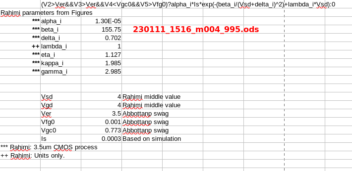
|
The parameters derived from the Cullinan and Rahimi presentation appear in the symbol model, discharge mode setup, and in various spreadsheet wargame analyses. |
|
Preliminary
Symbol Model 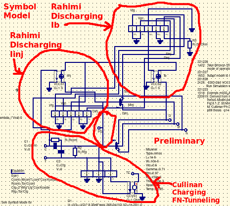
Discharge Setup 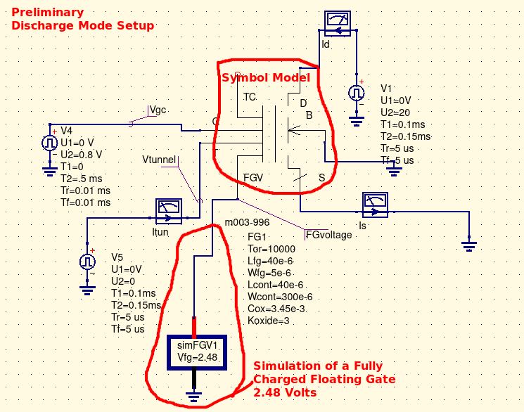
|
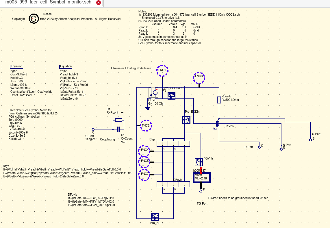
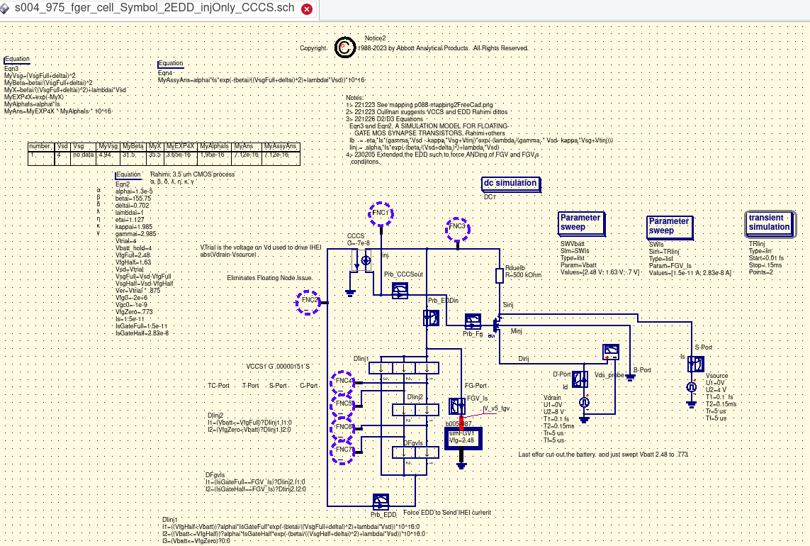
Inputs involving IHEI discharging derived from the Rahimi team's presentation were merged with those acquired from the Cullinan Thesis FN-tunneling
charging of the floating gate (schematic/symbol model and the simulation test setup). This model and simulation development
was performed using QUCS Equation Design Devices, and dependent sources.
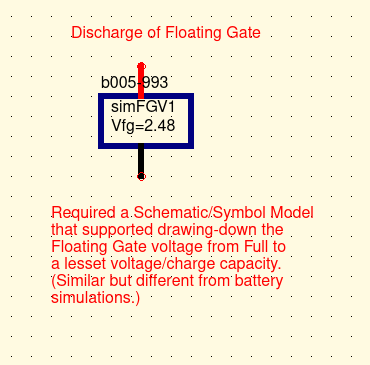
Critical to this effort was the realization that the floating gate once charged was serving as the powersource for the discharge. That demanded a bit of creative thinking and further study. QUCS did not have a 'ready made' power source to assume this role. |
Lost
|
After a suitable period of attempts using available QUCS components (EDD and dependent source devices) the search a solution moved to a wider scope. |
|
Found 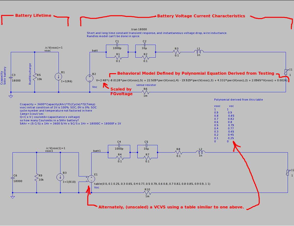
|
It appeared that the most likely pathway forward involved the adaption of an LTSpice model
for Lithium-Ion batteries. One pathway forward was presented in a youtube video
Model Lithium Ion Battery with LTspice by Mike Trupiano.
His presentation provided an excellent discussion regarding battery theory as well as models for simulation. His chosen simulation
tool was LTSpice. In responding to a viewer requesting for the LTSpice simulation netlist, Trupiano provided
the complete project's documentation of the simulation model. That "netlist" excuted without issue in a session of the
LTSpice application. To be useful for the Floating Gate Electron Reservoir Power Source project the 'Battery's netlist' provided by
Trupiano required a conversion to QUCS simulation syntax. The beauty of Trupiano's
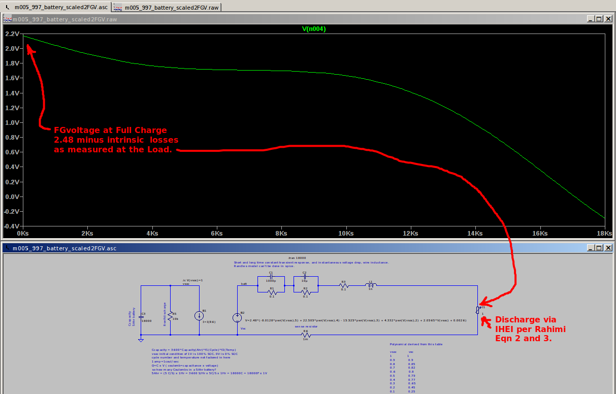
simulation model is that the discharge profile promised an appropriate mechanism demonstrating the decay of battery
capacity.
For a better understanding of the Trupiano LTSpice model and how it was rendered into a QUCS model refer to the following references:
|
|
The translation of the Trupiano's simulation model exhibited three voltage states (Full, Half, and Empty voltage levels). It also offered the opportunity to explore the "decay of the floating gate overtime" should it need ot be examined in the future. |
|
Spreadsheet 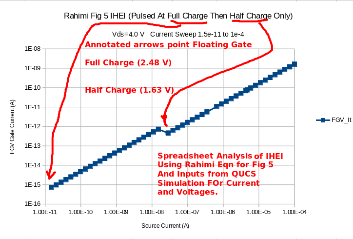
QUCS Equations 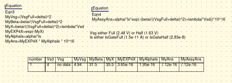
|
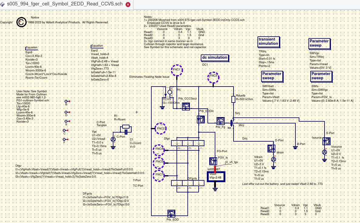
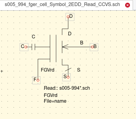
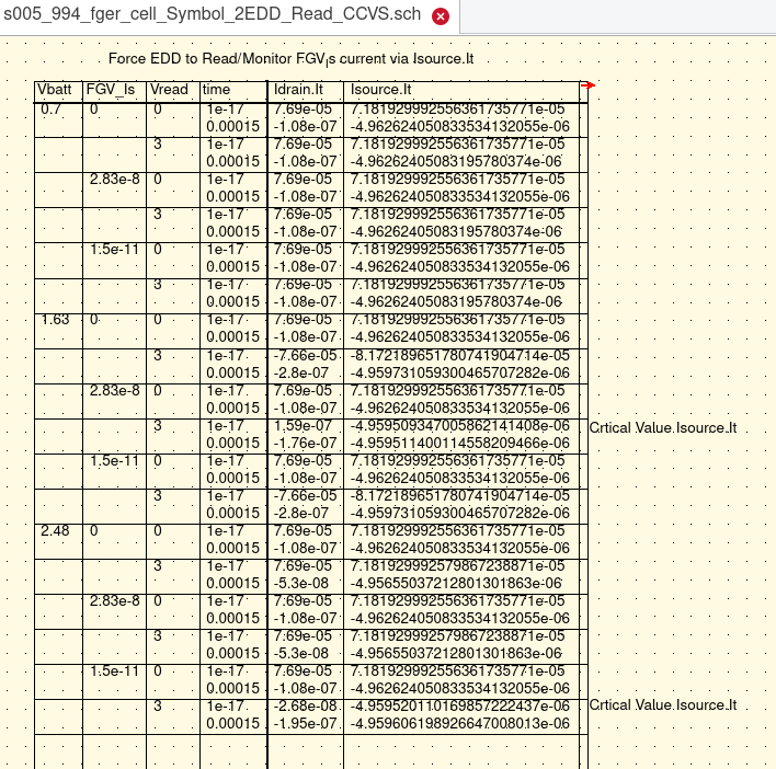
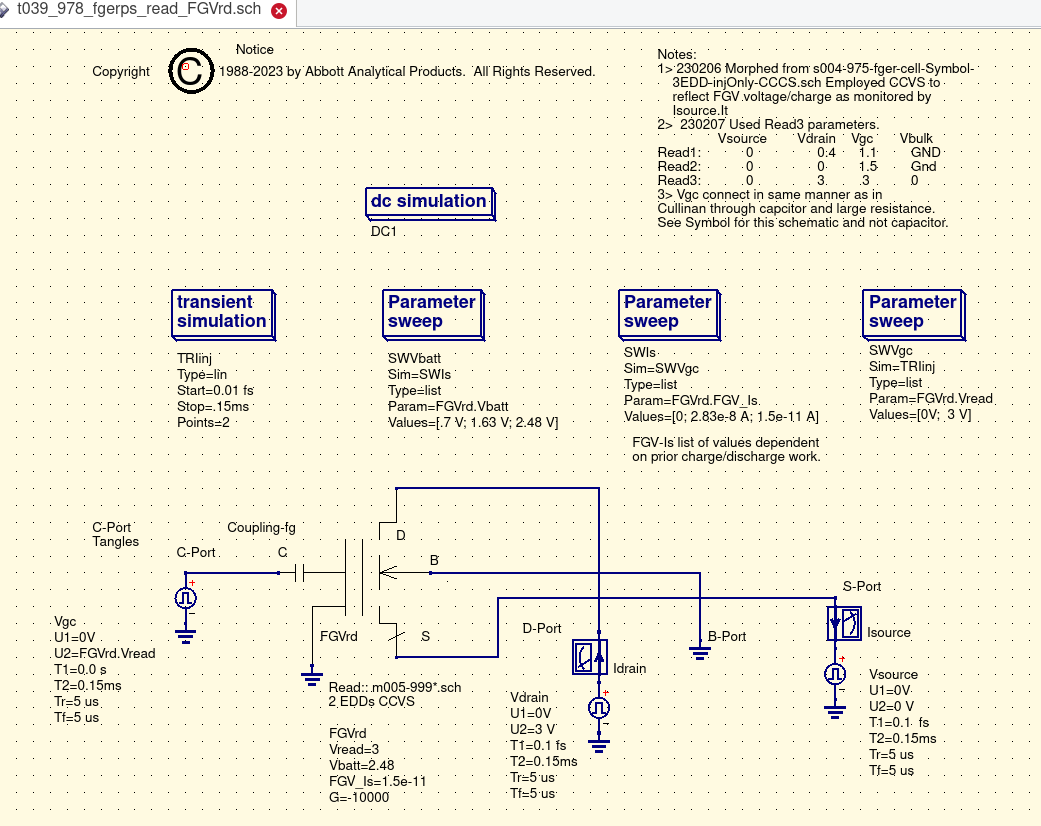
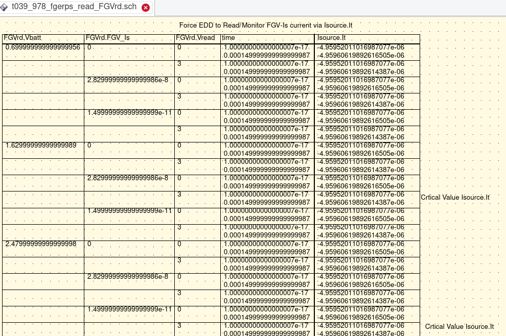
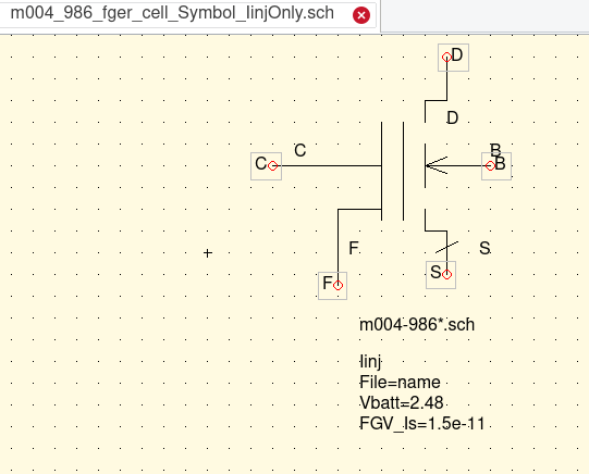
A suitable symbol representing a charged Floating Gate of the Floating Gate Electron Reservoir Power Source device was created. The model was integrated into the Floating Gate Electron Reservoir Power Source device. This allowed the usage of Parameter Sweep QUCS simulations under very fast time transisitons of (drain and source) voltage pulses. For the Parameter Sweep parameters of interest were the Floating Gate Voltage at Full and Half. The other parameter that was needed was the sweeping of the Floating Gate's current in the Full and Half states. These specific conditions were set and and controlled using the "list" input feature of the QUSC Parameter Sweep simulation. |
First Workable Ballpark
Derived IHEI Model 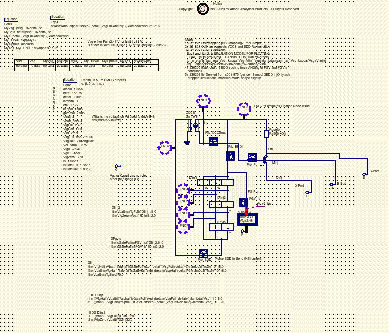
Simulation Test 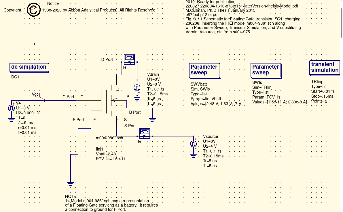
|
After finally reaching a schematic/model which provided 'ballpark' simulation of the IHEI contribution for discharging/erasing a project simplication decision was made. At this point in the project the contribution of the current cource from the well to the drain is going to be ignored. This decision/assumption will lead to a more conservative simulation estimate. As the project matures this decision may be re-visited. |

|
TBD |